BACnet Server
About BACnet Server
The server node serves the purpose of reading and writing values to the driver-bacnet. This functionality enables Rubix Compute to be integrated into a BACnet network.
See also: Tutorials BACnet-device The BACnet-server node serves two primary use cases:
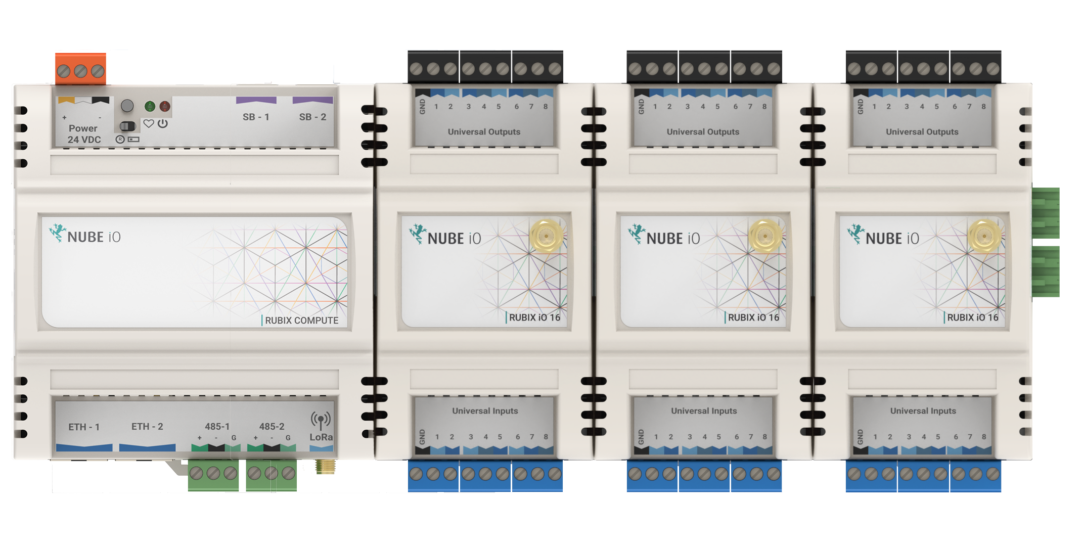
- Integrating hardware input/output (e.g., sensors and 0-10dc) into Rubix Compute by adding the Nube-IO IO-16.
- Adding proxy points (Analog Values and Binary Values) to the driver-bacnet. Before proceeding, ensure you have installed the required apps, particularly driver-BACnet.
In Rubix, you can't simultaneously add a Modbus network in the driver's settings and the BACnet-server node using the same serial-port. You have to choose one or the other, as they cannot coexist on the same port.
Setup
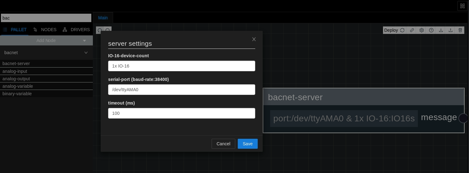
Add the bacnet-server node
- Open the Rubix Wires interface.
- Locate and select the option to add a new node.
- Choose the BACnet-server node from the available options.
- Configure the node by setting the number of IO-16s if applicable to your use case.
- Set the serial port according to your hardware setup.
- Save/Deploy the configuration.
Adding points
Following steps below allows you to effectively add points to the BACnet-server node in Rubix Wires.
- Open the BACnet-server node by right-clicking and selecting Open sub flow.
- Once inside, you can add nodes by right-clicking or dragging from the palette.
- Add a new node, selecting either
AI (Analog Input),AO (Analog Output), orAV (Analog Value). - Set the node name to specify the BACnet object name for the point.
Ensure to set the node name to accurately reflect the point name on the BACnet network.
BACnet point nodes
| Node Name | Category | Use Case | is writeable |
|---|---|---|---|
| analog-input | bacnet | Is only used when the IO-16s are added (will work with UIs) | read only |
| analog-output | bacnet | Is only used when the IO-16s are added (will work with UOs) | writeable via in14 & in15 |
| analog-variables | bacnet | to read and and write values to AVs on the bacnet-server, eg a set-point | writeable via in14 & in15 |
| binary-variables | bacnet | to read and and write values to BVs on the bacnet-server, eg an enable | writeable via in14 & in15 |
Adding IO-16s
Adding upto 4x IO16s will make the Rubix Compute a BACnet-ip IO device
Adding a AI or AO
In the flow-framework, there's no necessity to add a Modbus network to communicate with the IO-16s.
To configure the BACnet-Server with the desired number of IO-16s, you typically access the BACnet-Server settings interface and input the quantity of IO-16s you intend to add.
To proceed, a systematic outline of each step for adding UI-1 on IO-2 is as follows:
- Power down the Rubix Compute.
- Connect 2x IO16s to the Rubix Compute. Remember, the IO-16s are powered via the Rubix Compute.
- Set the dip switches on IO16 number 1 to address 1 and on number 2 to address 2. Ensure the baud rate is set to 38400 as well.
- Refer to the documentation for more info on setting up the IO-16s.
- Power up the Rubix Compute.
- Open the BACnet-server node.
- Add an Analog Input (AI) node to the BACnet-server configuration.
- Right-click on the newly added AI node and select
Settings. - Configure the IO Device Number to 2, indicating the 2nd IO-16.
- Set the UI Number to 1, representing UI1.
- This configuration will assign the Analog Input as AI9.
Given that the IO-16 utilizes UOs (Universal Outputs) and UIs (Universal Inputs), only AOs (Analog Outputs) and AIs (Analog Inputs) can be added.
But we can employ UI-1 as a DI (Digital Input), an AI node should be added and configured to address 1 (AI1). Subsequently, it should be set as a digital input.
To enable this functionality:
Add an AO (Analog Output) node and set its settings to operate in a digital mode. Configure the point to accept any value greater than 1 to activate the Digital Output (DO). For instance, the point should interpret values like true/false, 1/0, or 10/0 to control the DO.
UI/UO to BACnet Addressing
Example for inputs
| Device Address | IO Number | BACnet address |
|---|---|---|
| 1 | UI1 | AI1 |
| 1 | UI2 | AI2 |
| 1 | UI3 | AI3 |
| 1 | UI4 | AI4 |
| 1 | UI5 | AI5 |
| 1 | UI6 | AI6 |
| 1 | UI7 | AI7 |
| 1 | UI8 | AI8 |
| 2 | UI1 | AI9 |
| 3 | UI1 | AI17 |
This device addressing can be extended until you reach the limit of 4x IO1-6 devices.
Example for outputs
| Device Address | IO Number | BACnet address |
|---|---|---|
| 1 | UO1 | AO1 |
| 2 | UO1 | AO9 |
| 3 | UO1 | AO17 |