Wiresheet
Wiresheets allows you to create and manage wire-based programs for controlling and monitoring devices.
Adding Nodes
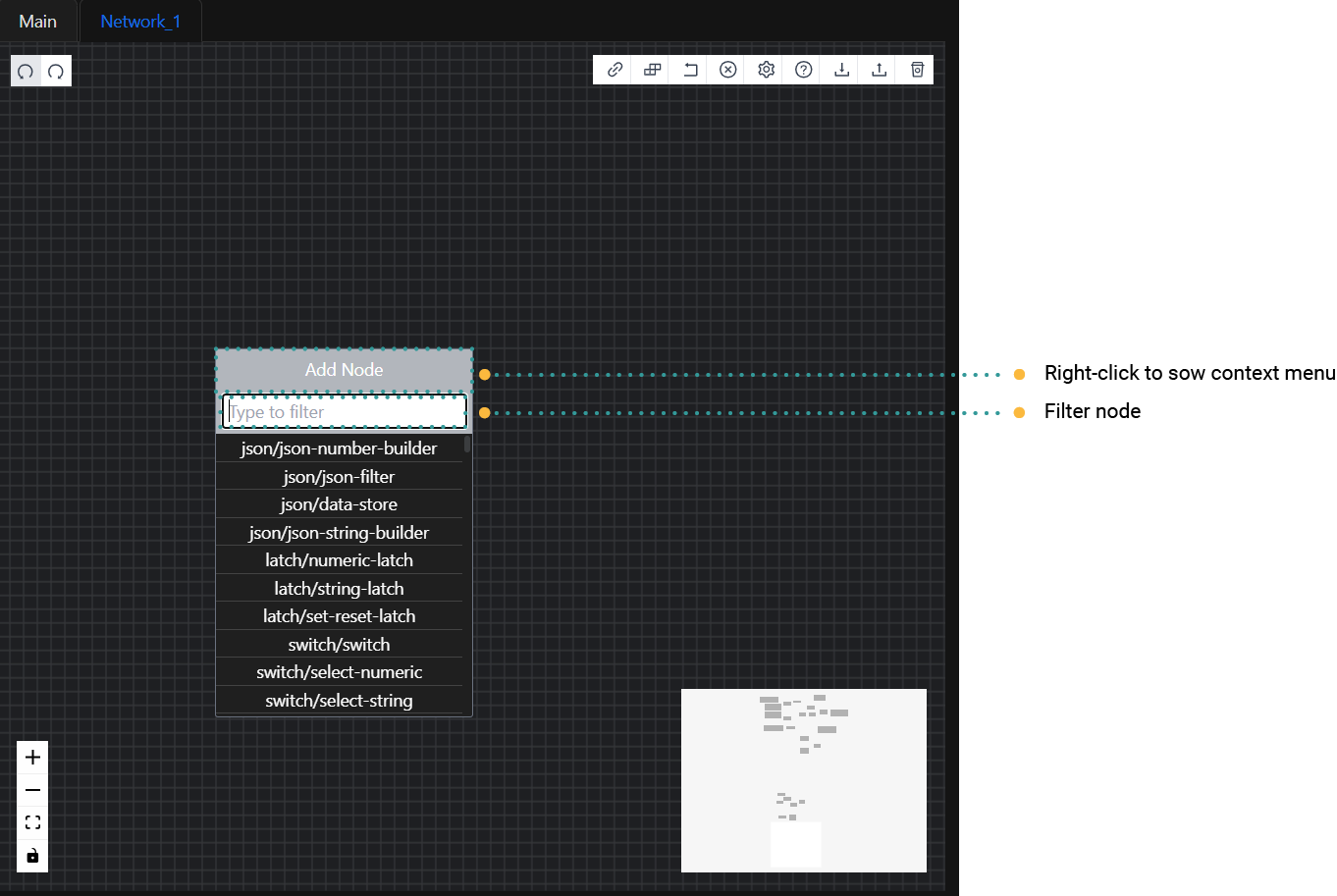
Adding Nodes from the Context Menu
To add nodes from the context menu in Rubix Wires, follow these steps:
- Right-click on the Editor Pane to open the Context Menu.
- Enter a keyword or term to filter the list of available nodes based on the group you want to add to the Editor Pane.
- From the filtered results, locate and click on the specific node you want to use.
- The selected node will then be added to the Editor Pane, where you can further configure and connect it as needed within your workflow.
Adding Nodes from the Node Palette
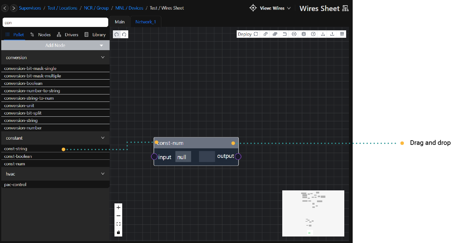
To add nodes from the Node Palette in Rubix Wires, follow these steps:
- Open the Node Pallet, which displays different node groups.
- Click on a node group to expand it, revealing the available nodes within that group.
- Locate the specific node you want to add to your workflow.
- Click and drag the desired node from the Node Palette to the Editor Pane.
- Release the mouse button to drop the node onto the Editor Pane.
- The selected node will now be added to the Editor Pane, where you can further configure and connect it as needed within your workflow.
Node Pallet Search
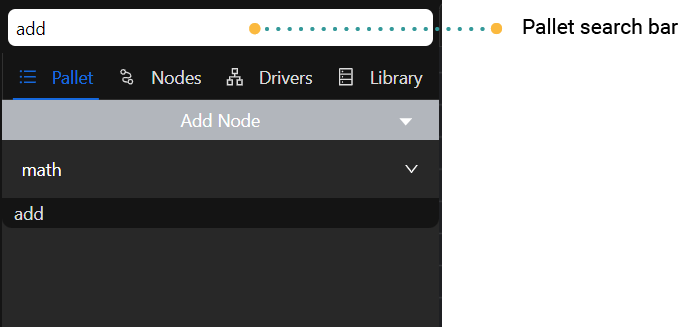
To facilitate finding nodes quickly in the Node Pallet, Rubix Wires offers a search feature located at the top of the Node Palette. Here's how it works:
- Locate the search bar at the top of the Node Pallet.
- Type your desired search term or keyword into the search bar.
- As you type, the Node Pallet will dynamically filter the nodes displayed, showing only those that match the search terms.
- Browse through the filtered nodes to find the one you're looking for.
- Once you find the desired node, you can click and drag it from the Node Palette to the Editor Pane to add it to your workflow.
Cloning nodes
Nodes can be cloned (duplicated) by selecting ctrl-d or by right clicking the node and selecting Duplicate Node
Removing Nodes
To remove nodes in Rubix Wires, you can use the following methods:
Remove a Single Node:
- Click on the node you want to remove to select it.
- Press the delete key on your keyboard. This will delete the selected node.
Remove Multiple Nodes:
- Hold down the shift key on your keyboard.
- Click on each node you want to remove while holding the shift key. This will select multiple nodes, and an outline will appear around each selected node.
- Once you have selected all the desired nodes, press the delete key on your keyboard. This will delete all the selected nodes simultaneously.
Instead of using the delete button on your keyboard, you can also remove a node by following these steps:
Right-click on the selected node or nodes within the editor interface.
Select Delete Nodes from the context menu that appears.
This method provides an alternative way to delete nodes from your workflow or configuration within the editor, offering flexibility in how you manage and manipulate elements within the workspace. It can be particularly useful for precise editing tasks or when working with multiple nodes simultaneously.
Node Settings
Each node on the Editor Pane in Rubix Wires has settings that can be configured to adjust its function or labeling. These settings are unique to each individual node and can be customised as needed.
Simply double-click on the node that you want to edit. This action will open up the settings interface for that particular node, allowing you to modify its configuration.
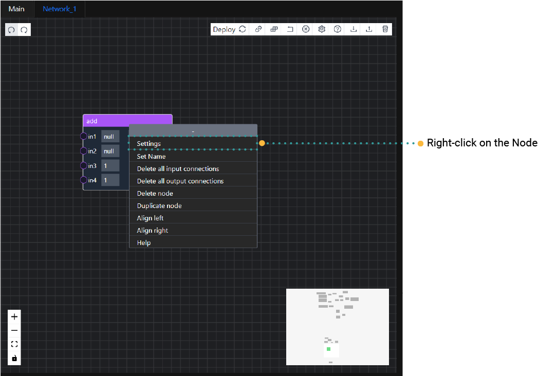
Alternatively, you can right-click on the node.
From the context menu that appears, select the Edit Settings option. This will open the settings interface for the selected node, where you can make the necessary adjustments.
Node Inputs and Outputs
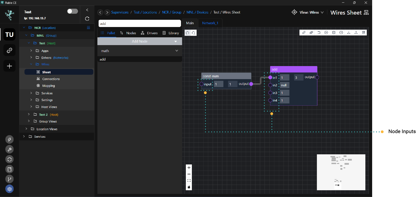
Nodes have various inputs and outputs depending on their specific function within the workflow. These inputs and outputs allow nodes to send and receive data, enabling the creation of complex logic and functionalities. Additionally, many nodes come with settings that can modify the available inputs and outputs, providing flexibility and customization options.
Node Inputs
Node inputs provide values to be used in computing the node’s outputs. Wire links can be connected to the left hand side
of node input slots. The image below shows the 4 inputs of a min-on-off node.
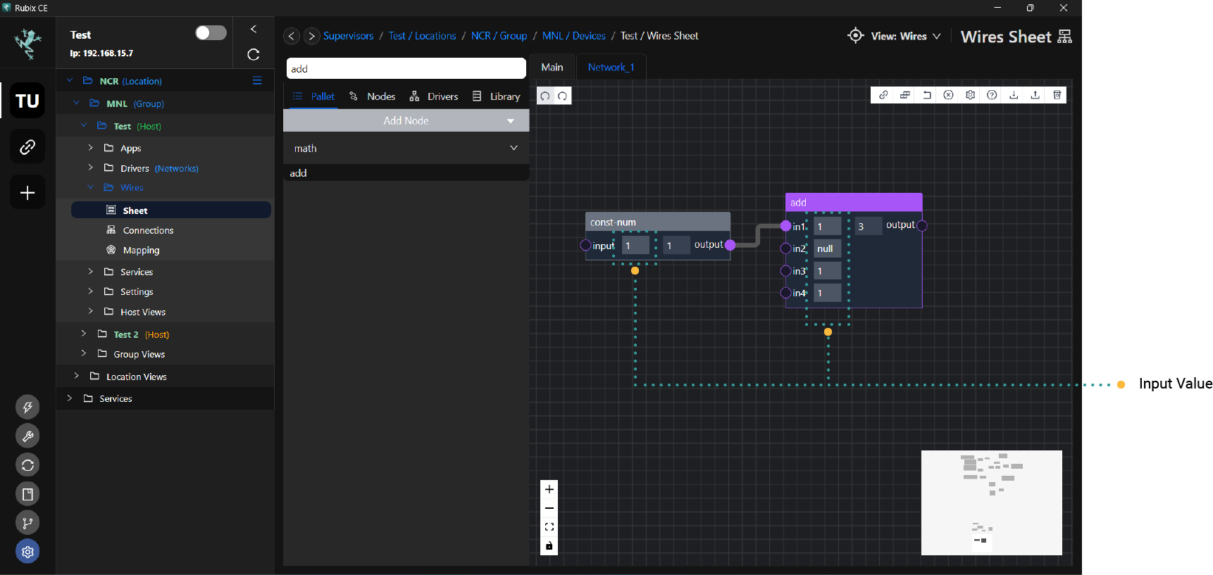
Node Inputs value
A node supports the option to write a value directly in the input rather than connecting in another node
Variable Input Counts
Many nodes have a setting which will create/remove node inputs.
Example of some nodes that support this: Math/Add Bool/And
To add an input to a node, you can specify the number you need by right clicking the nodes and selecting settings. Input the number of input count on the pop up box.

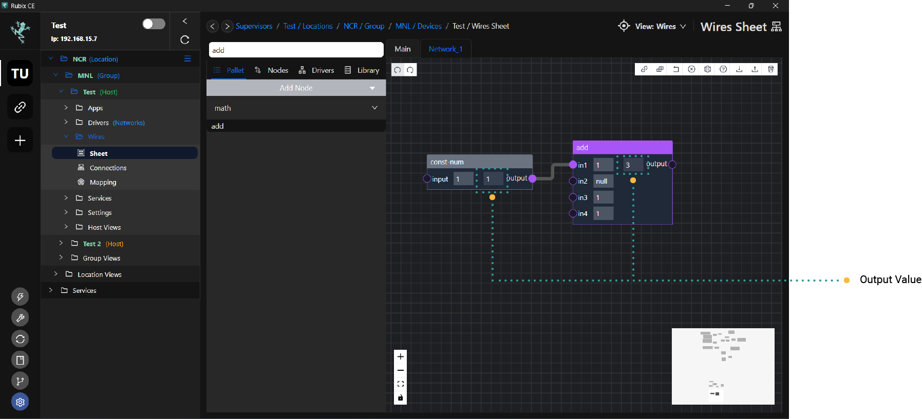
Node Outputs
Node outputs are the results of a nodes specific function. Wire links can be connected from the right hand side of node output slots. The image below shows the 1 output of a const-num node.
Adding Network Driver Points
Points from the network driver can be connected to the system points.
Directly from Drivers Pallet
- Click the Drivers tab on the wire sheet.
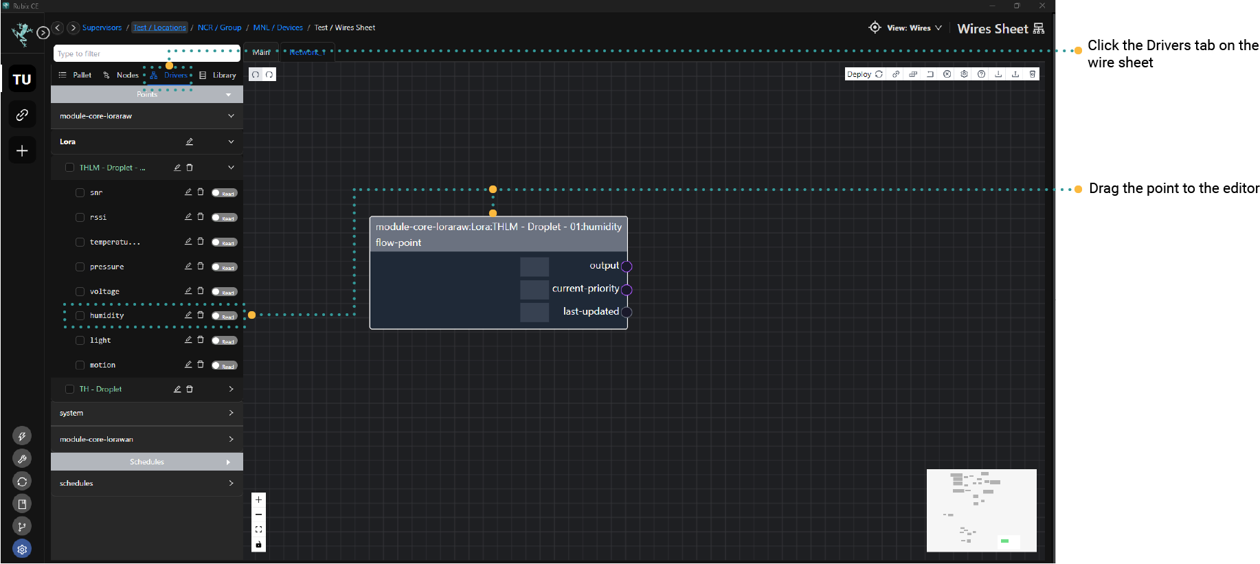
- Locate the driver you wanted to connect to system points.
- Expand the driver by clicking the arrow button.
- Drag the desired point from the network to the editor canvas. Network driver points may be configured as read-only or read-write.
- Connect the output of the network point to the system point you intend to link with. Refer to the sample image below for guidance.
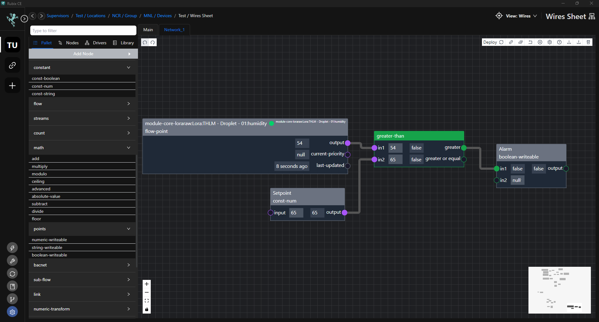
Using Flowpoint
- Drag the flow-point node from the Palette.
- Right-click on the node and choose
Settings. - From the list, select the desired point. The list is arranged based on the network configuration.
Creating Calculated Points
Calculated points may involve mathematical operations like addition, subtraction, multiplication, division, or more complex functions depending on the logic you wish to create.
- First, you will need to identify the input variables. These could be sensor readings, system parameters, or any other relevant data sources.
- Define the logic or calculation. Develop the logic or calculation that your calculated point will perform using the input variables. This could involve mathematical operations like addition, subtraction, multiplication, division, or more complex functions such as conditional statements or mathematical models.
- Lastly the output, this will be the result of the processed inputs.
Example of Calculated Points
Creating calculated points using system points
- Calculate the average value of multiple input variables.
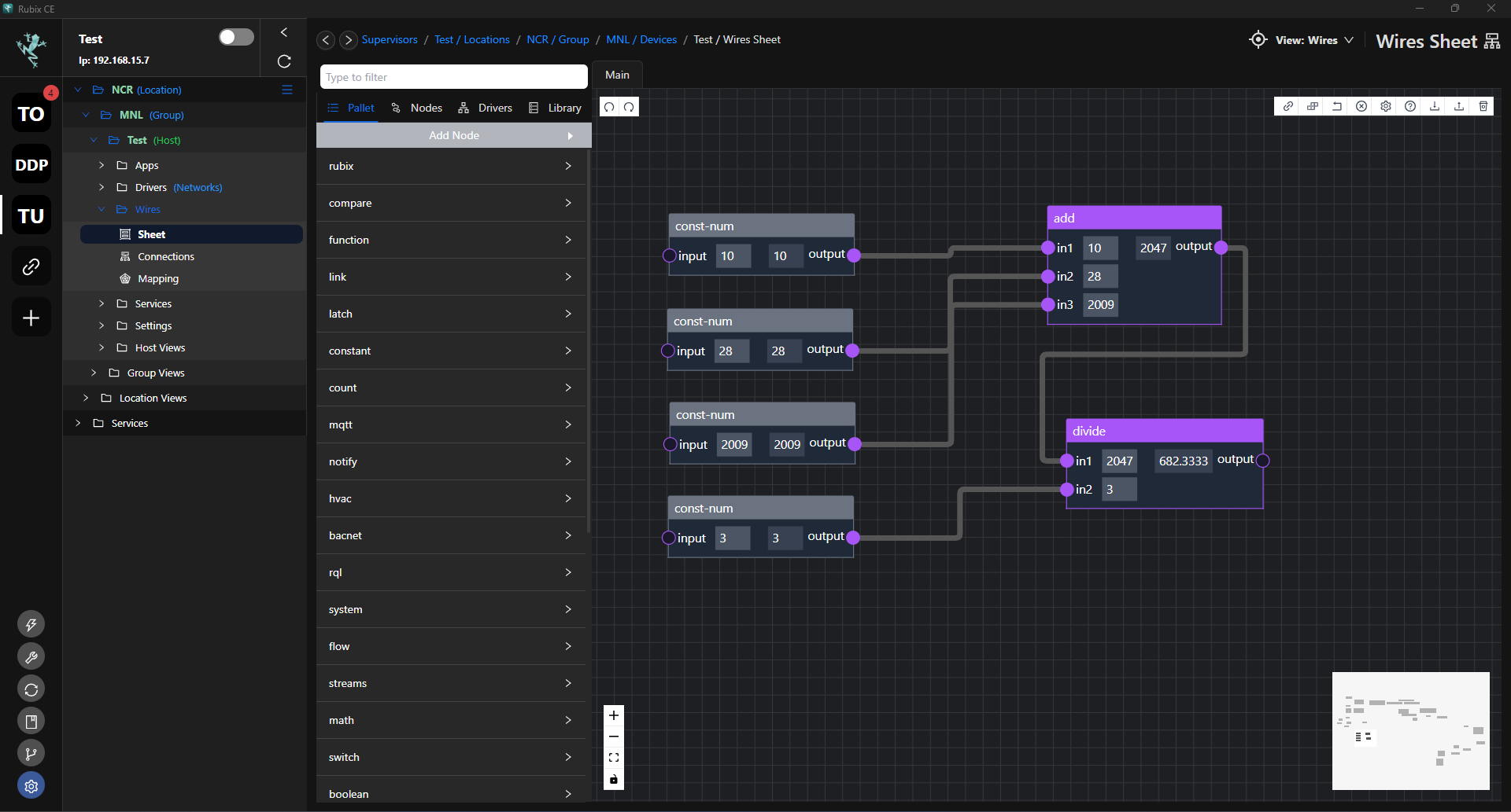
In this Logic:
- Input 1, Input 2, and Input 3 are connected to an ADD node, which sums them together.
- The output of the ADD node is then connected to a DIVIDE node, where Input 4 is used as the divisor.
- The result of the division is the output of the calculated point.
This logic represents dividing the sum of Input 1, Input 2, and Input 3 by Input 4.
Creating calculated points with network driver points
- Convert temperature from one scale to another (e.g., Celsius to Fahrenheit).
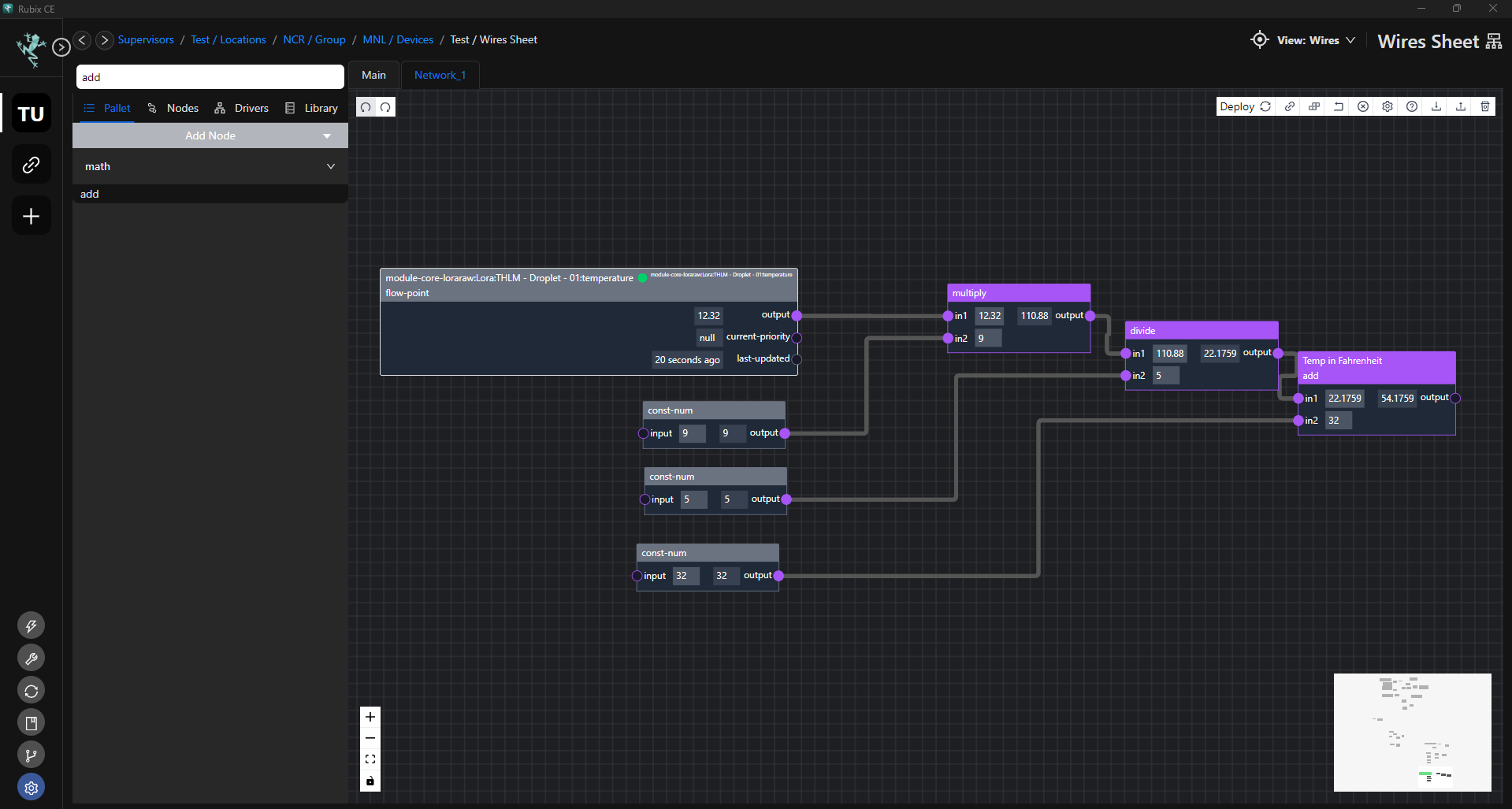
In this Logic:
Input (Celsius): This is the temperature value in degrees Celsius that you want to convert to Fahrenheit. It serves as the input variable for the calculation.
Multiplication by 9 and divide by 5: To convert Celsius to Fahrenheit, you multiply the temperature in Celsius by 9/5. This accounts for the difference in scale between Celsius and Fahrenheit.
Addition of 32: After multiplying by 9/5, you add 32 to the result. This is because 0 degrees Celsius is equivalent to 32 degrees Fahrenheit. Adding 32 shifts the temperature scale to match the Fahrenheit scale.
Output (Fahrenheit): The final result of the calculation is the temperature in degrees Fahrenheit. This serves as the output of the calculated point.