EMS System Troubleshooting Guide
Overview
Use this guide for quick on-site checks to identify power, network, sensor, and hardware issues before escalation. Checks are separated by role so the right person performs the right action safely.
Power supply unit (PSU) in this guide means the device providing low-voltage power to the gateway (typically a 24V power supply).
Safety and Role Boundary
- Facilities Manager: visual inspection, status checks, simple resets, cable reseat, battery replacement, and evidence collection.
- Licensed Tradesperson (Electrician/Plumber): live electrical testing, rewiring, supply rectification, terminations, and meter/sensor plumbing-electrical rectification.
- If there is water ingress to the gateway, burn marks, or exposed conductors, isolate equipment and escalate immediately.
Gateway (Rubix Compute)
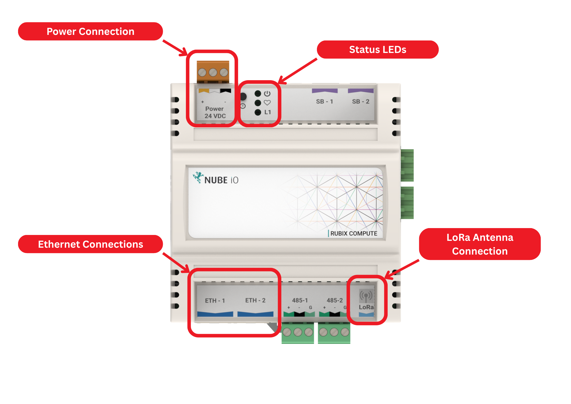
Use this image as a quick visual reference for the Rubix Compute check points:
- Power Connection: 24V DC power connection for the Rubix Compute.
- Status LEDs: Visual status indicators for power, activity, and communication state.
- Ethernet Connections: LAN ports used for wired network connections.
- LoRa Antenna Connection: RF antenna connection used for LoRa field-device communications such as Microedges and Droplets.
| No. | Check | Role | Symtom | Likely Cause | Action |
|---|---|---|---|---|---|
| 1 | Gateway Hardware Condition Check | Facilities Manager | Visible water ingress, burn marks, or loose wiring | Physical damage or installation fault | Isolate equipment and escalate to licensed tradesperson. |
| 2 | Gateway LED Check | Facilities Manager | No LEDs on gateway | Power not present | Check local breaker label/status, confirm 24V power supply is ON, and confirm connectors are seated. |
| 3 | Gateway LED Check | Facilities Manager | Solid Orange LED on gateway | Software/Pi not operational | Confirm connectors are seated correctly and powercycle the gateway. |
| 4 | Ethernet Link-Light Check | Facilities Manager | Gateway LEDs ON,Ethernet lights OFF | Network/router issue | Reconnect or replace Ethernet patch cable and reboot gateway/router. |
| 5 | 24V Supply Voltage Check | Licensed Tradesperson (Electrician) | Gateway still no power after basic checks | Failed 24V power supply (PSU), missing 24V feed, or wiring fault | Test supply voltage, polarity, and continuity; rectify feed/termination; replace failed 24V power supply. |
| 6 | Termination Integrity Check | Licensed Tradesperson (Electrician) | Loose or failed terminations | Installation fault | Re-terminate wiring to standard, torque-check terminals, and verify enclosure integrity. |
| 7 | Electrical Damage Check | Licensed Tradesperson (Electrician) | Burn marks or heat damage | Electrical fault/current event | Isolate circuit, replace damaged components, and verify protective device coordination. |
Router (USR-G806-AU)
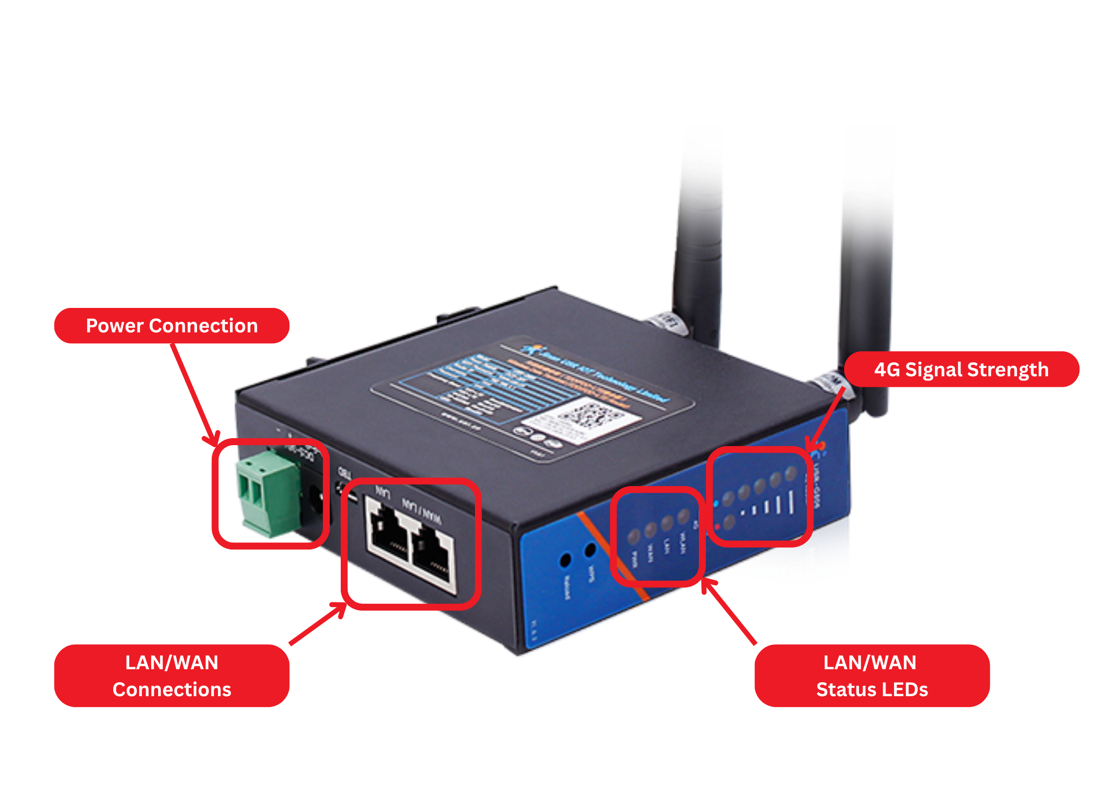
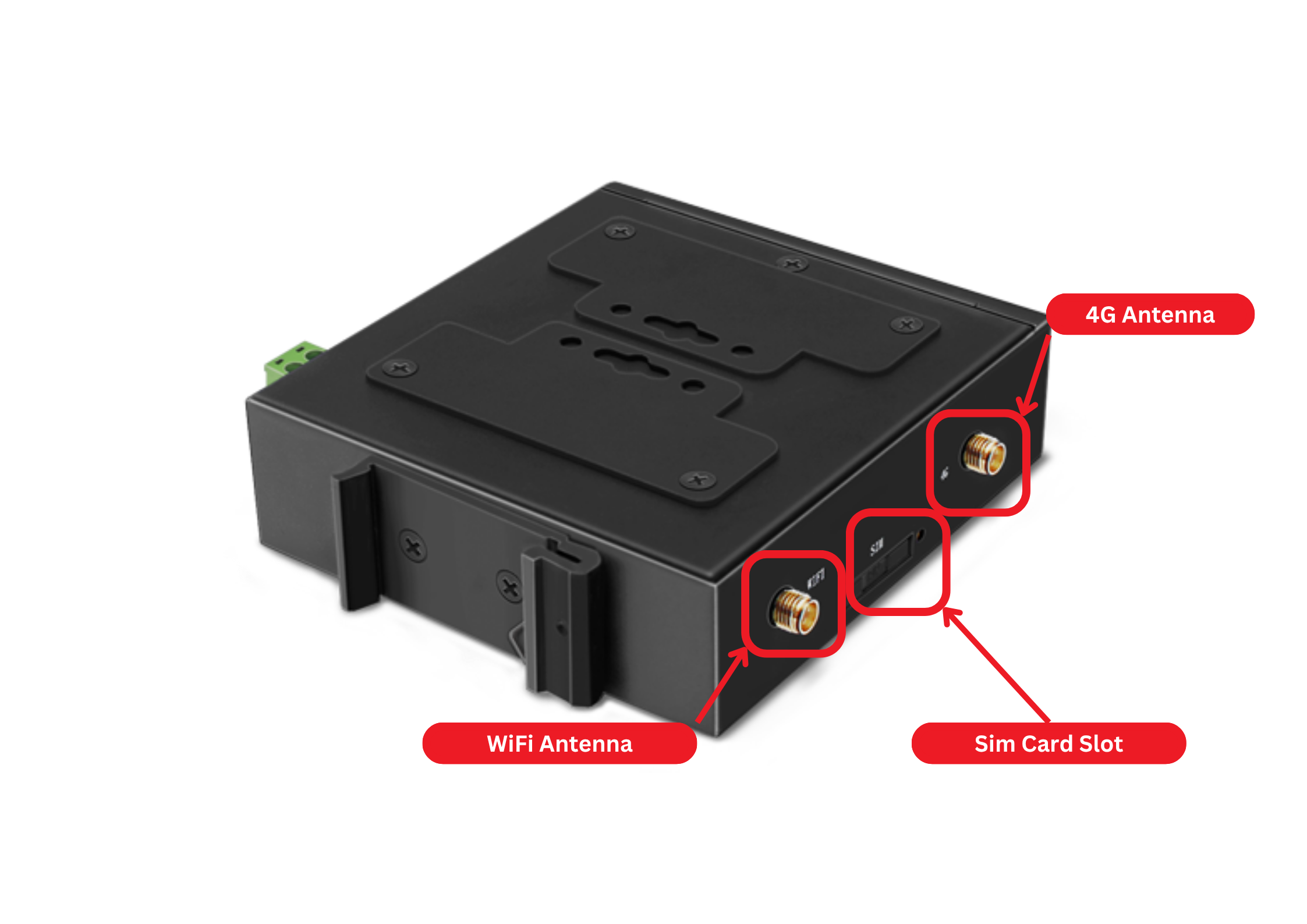
Use this image as a quick visual reference for the Rubix Compute check points:
- Power Connection: 24V DC power connection for the router.
- LAN/WAN Connection: Ethernet ports used for internet connectivity and connecting to the Rubix Compute.
- 4G Signal Strength: Visual status indicator for cellular signal strength.
- LAN/WAN Indicator: Visual status indicator for LAN/WAN network connectivity.
- 4G Antenna: RF antenna connection used for cellular communications.
- WiFi Antenna: RF antenna connection used for WiFi communications.
| No. | Check | Role | Symtom | Likely Cause | Action |
|---|---|---|---|---|---|
| 1 | Router Power Check | Facilities Manager | Router has no power | Failed 24V power supply (PSU), missing 24V feed, or wiring fault | Check local breaker label/status, confirm 24V power supply is ON, and confirm power connectors are seated correctly. |
| 2 | Router 4G Internet Check | Facilities Manager | Router no 4G internet | Sim/Connection issue | Check 4G antenna connection, reboot router once, confirm 4G signal indicators, and check for known sim outage. |
| 3 | Router Temperature Check | Facilities Manager | Router overheating | Ventilation or installation issue | Improve airflow (open enclosure lid slightly if not exposed to weather), remove obstruction to airflow, and monitor stability. |
| 4 | Router Supply Voltage Check | Licensed Tradesperson (Electrician) | Router still no power after basic checks | Failed 24V power supply (PSU) or wiring fault | Test supply voltage and polarity, rectify feed/termination, and replace failed supply hardware. |
Micro-Edge (LoRa Sensor)
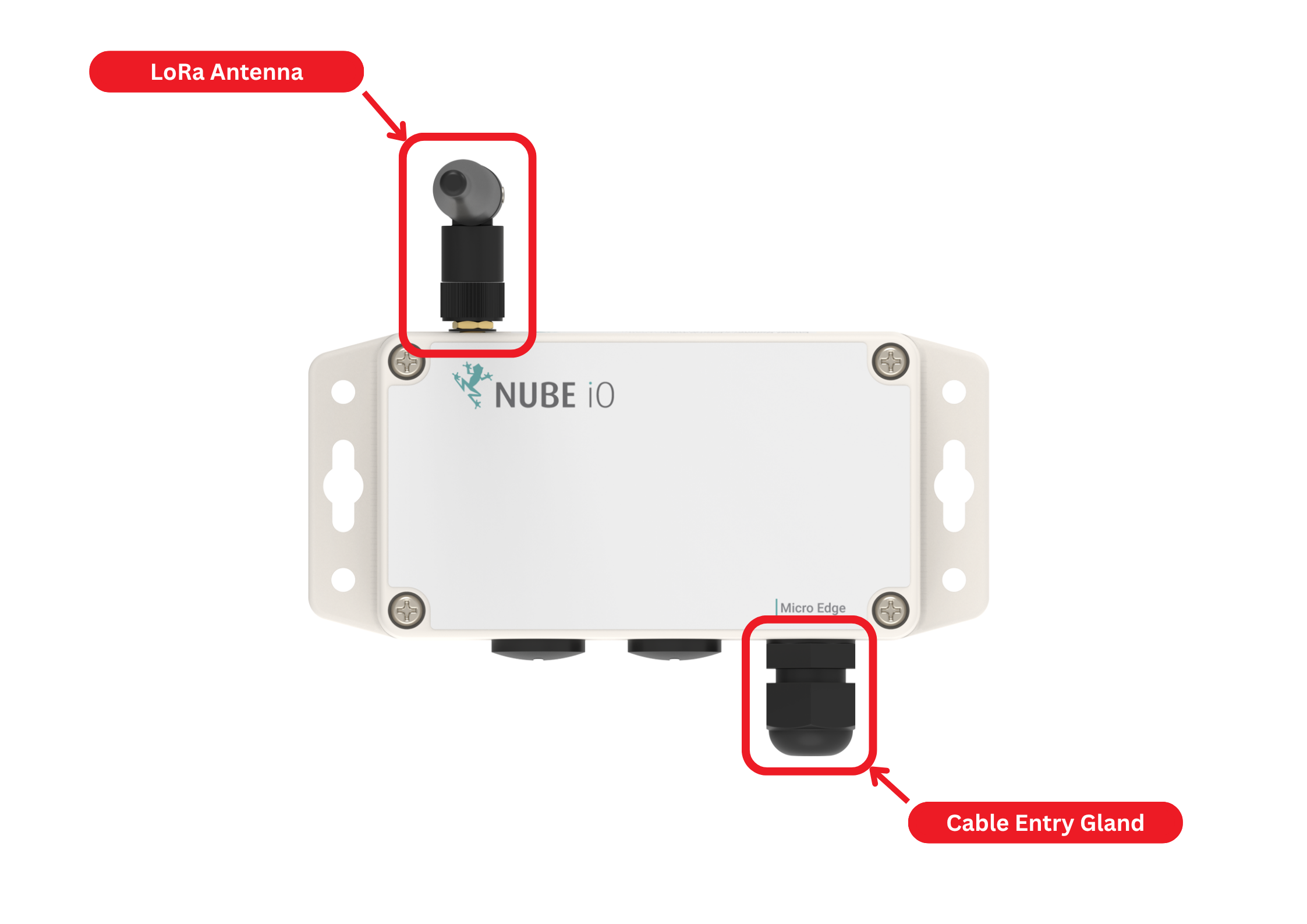
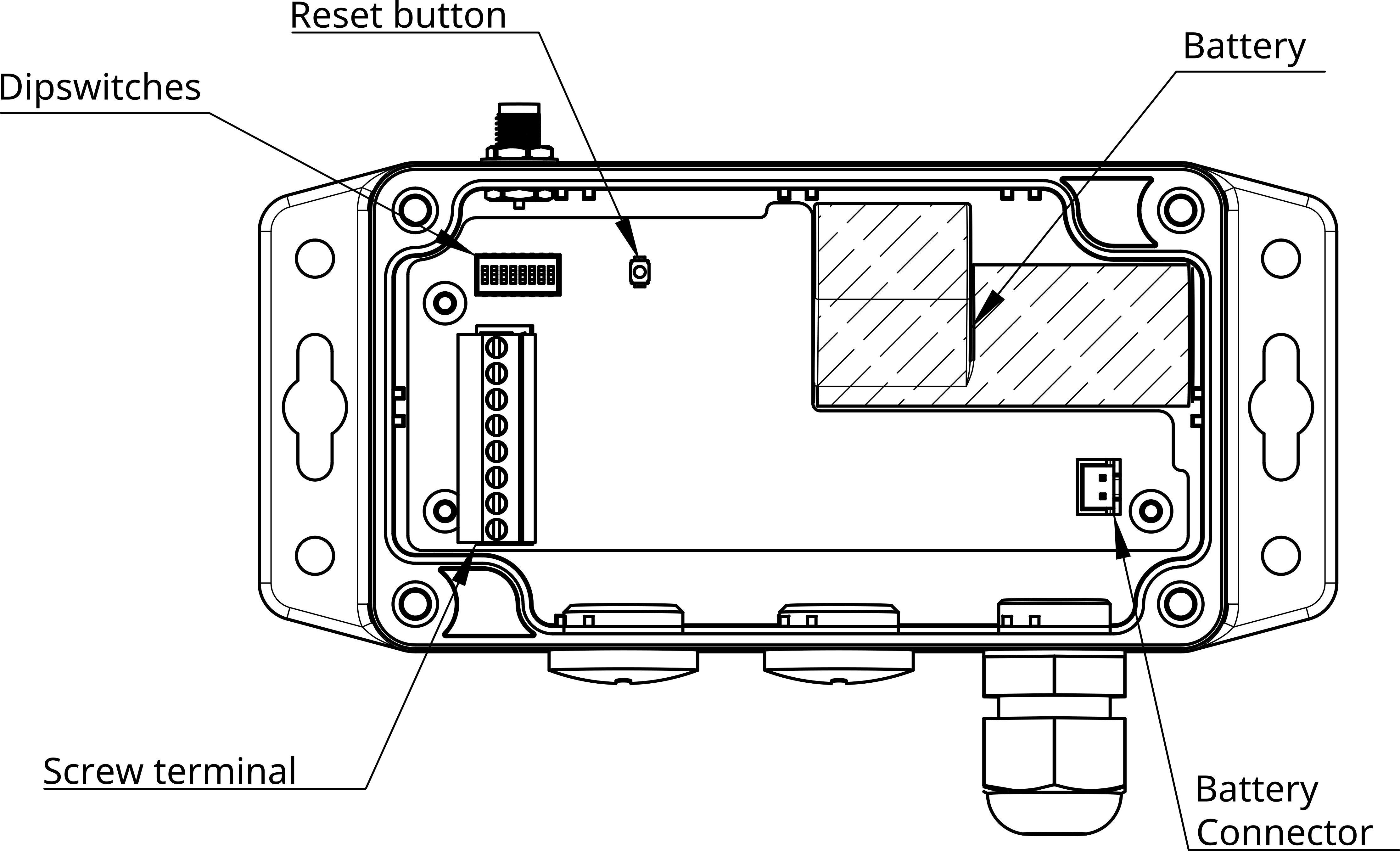
Use this image as a quick visual reference for the Micro-Edge check points:
- LoRa Antenna: RF antenna connection used for LoRa communications with the gateway.
- Cable Entry Gland: Sealed entry point for sensor cables, providing ingress protection.
- Reset Button: Physical button used for resetting the sensor to restart device operation.
- Battery: Internal 3.6V 4000mAh battery providing power to the Micro-Edge.
- Battery Connector: Connection point for the battery.
- Screw Terminals: Connection points for sensor wiring, such as pulse inputs from a water meter.
| No. | Check | Role | Symtom | Likely Cause | Action |
|---|---|---|---|---|---|
| 1 | LoRa Signal/Antenna Check | Facilities Manager | Intermittent data | Weak signal | Check antenna connection and for damage, reposition sensor/antenna to better location, recheck reporting. |
| 2 | Battery Health Check | Facilities Manager | Micro-Edge not reporting or low battery alarm | Battery depleted or poor battery contact | Disconnect/Reconnect battery and check for LED activity, check battery and terminal for corrosion, replace battery, recheck reporting. |
| 3 | Micro-Edge Reporting Check | Facilities Manager | Micro-Edge no data | Battery or LoRa path issue | Press reset button (RST) and check LED activity, replace battery if necessary and recheck reporting. |
| 4 | Battery Health Check (In Depth) | Licensed Tradesperson (Plumber/Electrician) | Micro-Edge not reporting or low battery alarm | Battery depleted or poor battery contact | Check battery voltage, replace battery and recheck reporting. |
| 5 | Meter Orientation/Install Check | Licensed Tradesperson (Plumber/Electrician) | Incorrect water/flow readings | Sensor install/config issue | Verify meter orientation, installation condition, wiring pulse/config, then redo rate of change validation. |
| 6 | Field Device Wiring Check | Licensed Tradesperson (Plumber/Electrician) | Persistent no flow data from field device | Field wiring/device failure | Test loop/pulse/wiring path (remove pulse wiring and bridge inputs to test pulses), rectify wiring faults, and replace failed field device. |
| 7 | Ingress Protection Check | Licensed Tradesperson (Plumber/Electrician) | Water ingress at enclosure/device | Seal or gland failure | Replace compromised parts, reseal glands/enclosure, and verify ingress protection. |
Contact Nube iO Support When
- Facilities Manager checks are complete and issue persists.
- Licensed tradesperson rectification is complete but telemetry is still missing/incorrect.
- Gateway and network are healthy but field devices still do not report.
- Repeated faults occur after rectification.
Email: service@nube-io.com
Phone: +(61) 279 068 414
Field Notes Template
Use this section when contacting Nube iO support:
- Site name:
- Date/time:
- Contact person:
- Gateway serial/Build ID:
- Affected device(s):
- Symptoms observed:
- Facilities Manager checks completed:
- Licensed trade checks completed:
- Actions taken:
- Photos attached: