Electrical Meter Installation and Commissioning Guide
1. Powering and Installing the Gateway
This section will outline the process required to power and install the gateway.
1.1 Re-attaching the Aerials
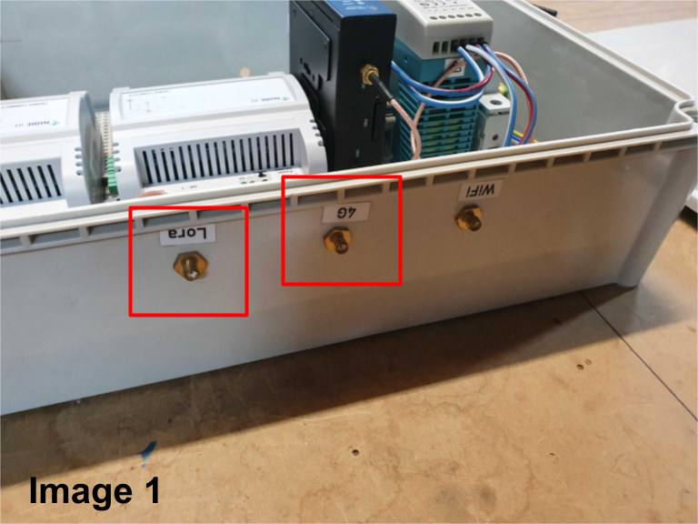
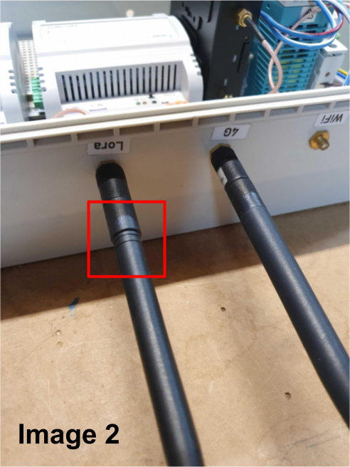
Before powering on the gateway, ensure the LoRa and 4G aerials are securely screwed into their correctly labeled ports on top of the gateway. The LoRa aerial is identifiable by two lines around its base (see Images 1 and 2).
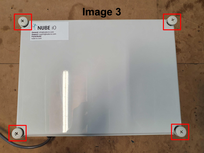
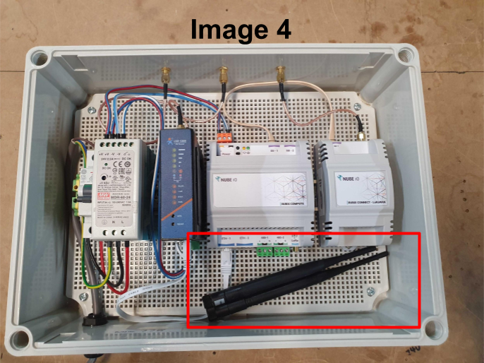
The aerials are stored inside the enclosure during shipping to prevent damage. To access them, unscrew the four corner screws on the enclosure lid (these are only finger-tight when shipped). (See images 3 and 4)
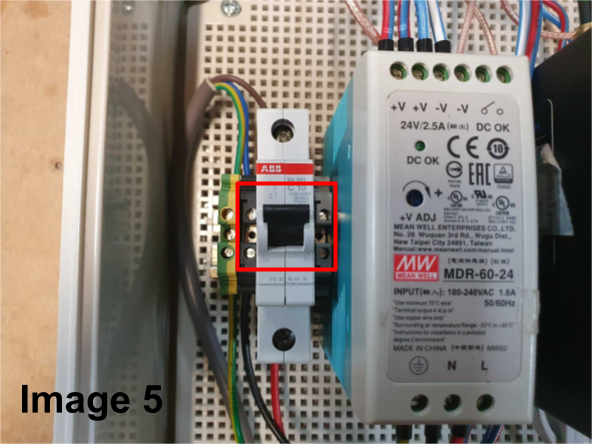
During this step confirm the circuit breaker is in the 'ON' position before re-installing the enclosure lid. The up position is when the circuit breaker is ON. (See Image 5)
1.2 Installing the Gateway
If securing the gateway to a wall, use four fixings - one in each corner of the enclosure. The choice of fixings will depend on the wall material.
If wall-mounting is not required, ensure the gateway is stored in a safe and secure location, free from any stress on the power cable.
1.3 Powering the Gateway
The gateways come with a pre-wired 3-pin plug. Simply connect this to a power outlet and switch it on. Allow up to 5 minutes for the 4G router and Rubix Compute to power up completely.
2. Modbus Connection
The Nube-iO Energy Monitoring System is compatible with Modbus RTU (Serial RS485) and Modbus TCP electrical meters.
2.1 Modbus RS485 Meters
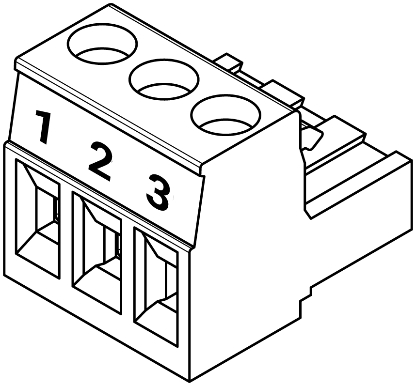
To establish communication with Modbus RS485 meters to a Rubix Compute, the Rubix Compute RS485 connectors are terminated and installed as shown below.
 | |
|---|---|
| Pin 1 (+) | A or + of RS485 Network |
| Pin 2 (-) | B or - of of RS485 Network |
| Pin 3 (G) | C or Ground |
Follow the manufacturer instructions for wiring and configuring the RS485 connection on the meter end.
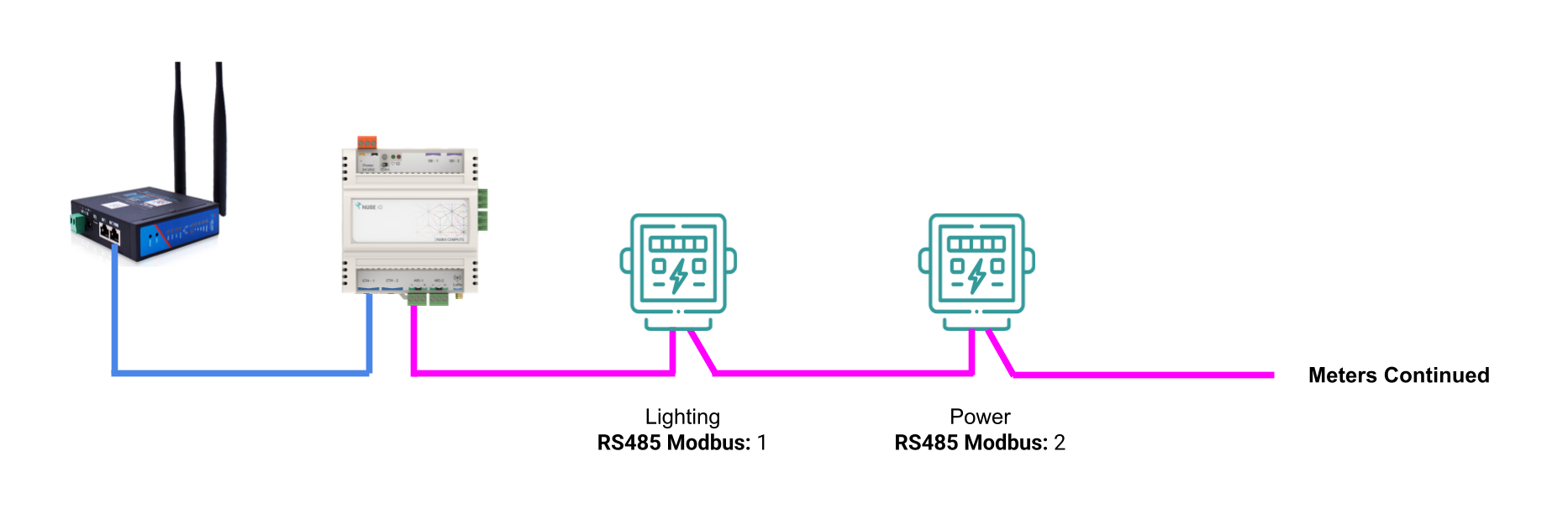
When wiring an RS485 network a single shielded twisted pair (STP) cable should be used and each meter MUST be connected in a Daisy Chain. Meters that are connected between 2 other meters will have 2 wires (one from the previous meter and one from the next meter) in the same terminal.
For optimal performance when connecting an RS485 network, the last device on the network should have an End Of Line (EOL) resistor installed.
Polarity of the A/+ and B/- wires must be kept consistent for all meters on the network.
See example network topology below.
2.2 Modbus TCP Meters
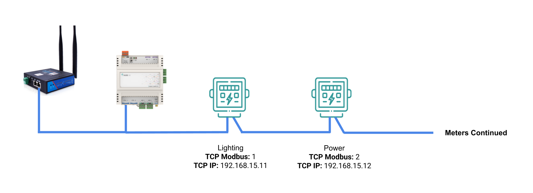
To establish communication with Modbus TCP meters to a Rubix Compute, the meter must be connected to the same network as the Rubix Compute. Follow the manufacturer instructions for wiring and configuring the Ethernet connection on the meter end. The meter must be configured with a static IP address.
Contact Nube iO support (service@nube.io.com) for the configured IP addresses of the Rubix Compute to confirm the meter is on the same subnet as the Rubix Compute. The default configuration for the 2 x Ethernet ports on the Rubix Compute is shown below.
| Port Name | Linux Port Name | Type | IP | Subnet | Gateway |
|---|---|---|---|---|---|
| ETH-1 | eth0 | Fixed | 192.168.15.10 | 255.255.255.0 | 192.168.15.1 |
| ETH-2 | eth1 | DHCP | Dynamic | Dynamic | Dynamic |
See example network topology below.
3. Electrical Meter Commissioning
The Electrical Meter Commissioning process involves configuring and commissioning the meter, then verifying the readings are correct.
3.1 Electrical Meter Configuration
Follow the manufacturer instructions for configuring the electrical meter. This will involve configuring the following parameters:
- Modbus address
- TCP IP address (for Modbus TCP meters)
- Baud rate (for Modbus RTU meters)
- Parity (for Modbus RTU meters)
- Data bits (for Modbus RTU meters)
- Stop bits (for Modbus RTU meters)
3.2 Electrical Meter Commissioning
The Electrical meter must be commissioned to ensure it is correctly reading and reporting the required parameters. This involves configuring the following:
- Voltage references
- Current transformer connection type (eg 2 CT, 3 CT, Single-Balanced CT, etc)
- Current transformer ratios (CT Ratios)
Note some smart meter models have the capability to auto-detect CT ratios and CT connection type, refer to the manufacturer instructions for details.
Once the meter is configured, confirm the meter is correctly reading the required parameters such as voltage, current, power, energy, etc. Refer to the manufacturer instructions for how to access these readings on the meter.
| Parameter | Acceptance Criteria |
|---|---|
| Voltage | Should be checked to be +/- 10% of nominal voltage (eg 230V) |
| Frequency | Should be checked to be +/- 10% of nominal frequency (eg 50Hz) |
| Current | Should be checked with a clamp meter or similar device to confirm it is reading the current correctly. |
| Power | Should be checked to be approximately equal to Voltage x Current (allowing for power factor). MUST be positive when load is connected. |
| Energy Import | Should be checked to be increasing when load is connected. Should be recorded in kWh. |
| Reactive Energy | Should be checked to be increasing when load is connected. Should be recorded in kVArh. |
4 Nube iO Remote Meter Reading System (RMRS)
Once the electrical meter is configured and commissioned, the meter should be added in the Nube iO RMRS as per the configuration set in section 3.1.
4.1 Confirming Meter Communication
After the meter is added in the Nube iO RMRS confirm the meter is communicating with the Rubix Compute.
If the meter is not visible, refer to the EMS System Troubleshooting Guide for steps to identify and rectify communication issues.
4.2 Confirming Meter Readings
Once the meter is communicating with the Rubix Compute, confirm the readings in the Nube iO RMRS are correct by comparing them to the readings on the meter display and/or readings from a clamp meter or similar device.
Values from both the RMRS and the meter display MUST be recorded for voltage, frequency, current, power, and energy to confirm the RMRS is accurately polling these parameters from the meter. This verifies correct point to point mapping of the meter registers and correct point scaling in the RMRS.
Values MUST be within the acceptable ranges outlined in section 3.2 and the power reading in the RMRS MUST be positive when load is connected.
| Parameter | Acceptance Criteria |
|---|---|
| Voltage | Should be checked to be +/- 10% of nominal voltage (eg 230V) |
| Frequency | Should be checked to be +/- 10% of nominal frequency (eg 50Hz) |
| Current | Should be checked with a clamp meter or similar device to confirm it is reading the current correctly. |
| Power | Should be checked to be approximately equal to Voltage x Current (allowing for power factor). MUST be positive when load is connected. |
| Energy Import | Should be checked to be increasing when load is connected. Should be recorded in kWh. |
| Reactive Energy | Should be checked to be increasing when load is connected. Should be recorded in kVArh. |
4.3 Energy Rate of Change Validation
To further validate the meter readings in the RMRS, the rate of change of energy MUST be validated to confirm the Energy consumption reported in the RMRS is consistent with the meter readings and the load connected.
This is done by recording the energy reading at two different time intervals and confirming the change in energy over time is consistent between the RMRS and the meter display.
5. Solar Metering
Solar metering involves the same process as outlined in sections 1-4, however power and energy readings may differ from the expected values in sections 3.2 and 4.2 as it may be flowing back into the grid depending on the load and generation at the time of testing and the meter configuration.
When commissioning solar meters, it is important to confirm the power readings polarity as the readings may be negative when power is flowing back into the grid. If power readings are negative the energy generation readings must be taken from the export point in the RMRS and not the import point. The export energy readings MUST be increasing when power is flowing back into the grid.
6. Contacting Support
If further assistance or support is required please contact Nube iO's service channel using the below details:
Phone: 0499 949 449
Email: service@nube-io.com