Modbus TCP
Getting Started
This article explains how to configure the Modbus TCP within Rubix CE. This will allow us the send and receive Modbus data from connected Modbus devices.
Adding a Modbus TCP Network
- Step-1 On the controller level, under
drivers, click the create to select and download and install the relevant network.
 - Step-2 Select the Modbus Network . This will download the appropriate modules and drivers.
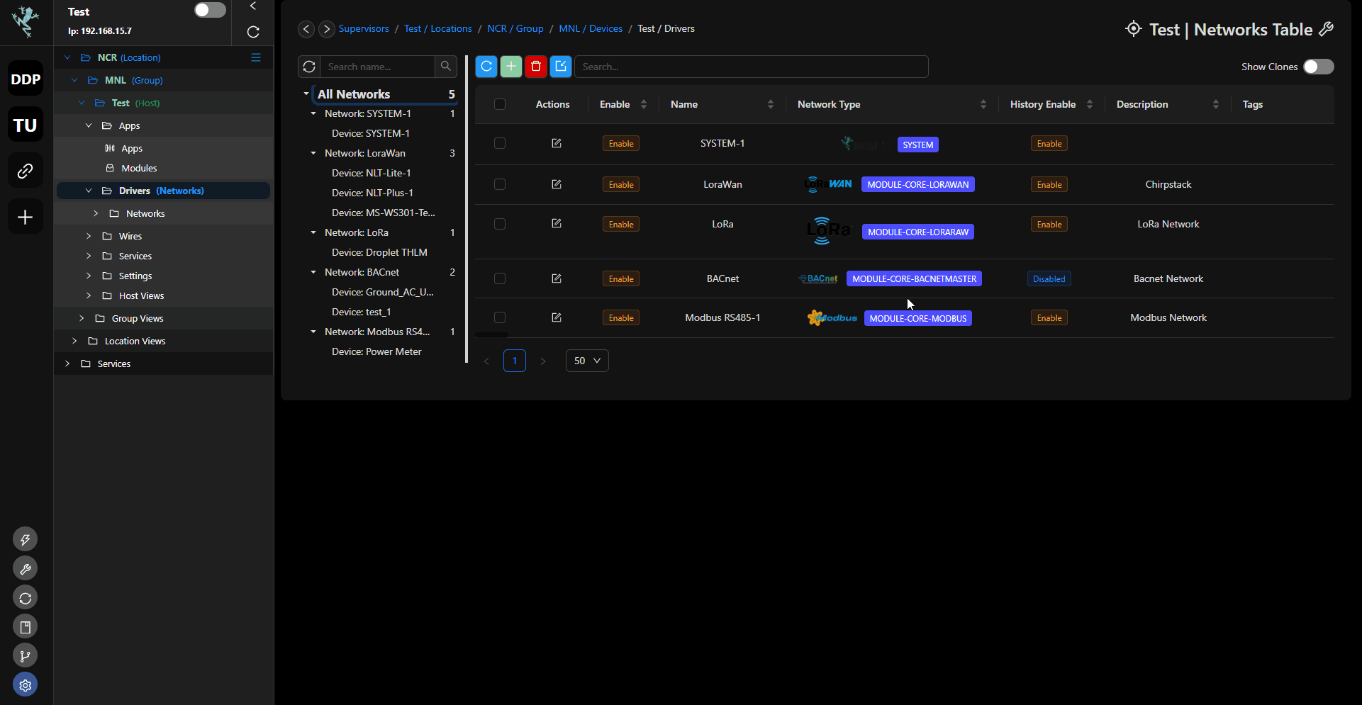
- Step-3 Configure the Modbus Network. Add the network name, network description and choose
IPon Network Transport Type, you can also turn ON the History if needed. Disregards other settings. - Step-4 Once all the settings are configured click on Create Network button. This will now create the Modbus and network. Now open the Modbus network to add a device.
| Attribute | Description |
|---|---|
| Name | Name of the network |
| Description | Description of the network, eg: level 1 network |
| Port | Default port is 502 you can also set it to another port if required. |
| Enable | Enable the network |
| Network Transport Type | Protocol used to physically transport Modbus messages between devices. This can be Serial, IP or LoRa |
| Serial Port | For Serial network only, physical connector on a device that facilitates serial communication. use /dev/tty/RS485-1 / /dev/tty/RS485-2 RTU ports. respectively. For wireless Modbus-Over-LoRa® Network, use /data/socat/serialBridge1. |
| Serial Baudrate | For serial network only, rate at which data is transmitted over a serial communication link, must match for all devices on the Modbus Network |
| Serial Data Bit | Number of bits used for each character in the communication (typically 8 bits in Modbus), must match for all devices on the Modbus Network |
| Serial Stop Bit | Signal bit that denotes the end of a data frame (usually 1 stop bit in Modbus), must match for all devices on the Modbus Network |
| Serial Time Out | Maximum wait time for a response from another device (critical for error handling) |
| Max Poll Rate | Maximum time, in seconds, for sending requests to slave devices (depends on network conditions and system requirements). |
info
Important things to note before proceeding: You must have a Rubix Compute and a modbus RTU device and know the settings required to add the device User Manual
Adding a Modbus Device in the Network
- Step-1 On Modbus Network, under
drivers, click the create new device. - Step-2 Fill out the details in the pop-up window with the correct information for the device you are adding. Information such as device name, Address ID, Host IP Address and Port. Click
Saveto confirm.
| Attribute | Description |
|---|---|
| Name | Name of the device |
| Description | Description of the device, eg: sensor 1 |
| Enable | Enable the device |
| Host IP | Fill in for Modbus IP only, IP of the device you wanted to connect with |
| Port | Modbus IP only, Default port is 502 you can also set it to another port if required. |
| Fast Poll Rate | Refers to the shortest interval or fastest frequency at which the Modbus master sends requests to the Modbus slaves for data. A fast poll rate means that the master device queries the slaves more frequently. |
| Normal Poll Rate | A moderate interval or frequency for polling Modbus slave devices. It’s a balanced approach where the master requests data at a rate that is frequent enough for timely updates but not as fast as the "Fast Poll Rate." |
| Slow Poll Rate | Longer interval or slower frequency for polling Modbus slaves. A slow poll rate means that the master device queries the slaves less frequently. This might be used in applications where the data doesn't need to be updated very often, or to reduce network traffic and conserve bandwidth. |
| Zero Mode | Refer to a mode where polling is effectively disabled or set to a very slow rate, potentially even stopping polling altogether. It could be used in scenarios where periodic polling is unnecessary or where the system is in a standby state. |
| History Enable | Enable device history |
| Tags | Right-click the network then tags, meta-tags to add in query key words |
| Meta-Tags | Right-click the network then tags, meta-tags to add in query key words |
| Message | See Troubleshooting for list of messages |
| State | last_ok: Indicates the time since the system has been error-free. |
last_fail: Specifies the date and time of the most recent occurrence of a failure. |
Adding Points to the Modbus Device
- Step-1 Locate the device you want to add points to from the list under the Modbus network. Right-click to open its settings.
- Step-2 Click the create new point .
- Step-3 Provide the necessary details in the pop-up window based on the device's manufacturer documentation for Modbus registers. Click the
Savebutton to finalize.
| Attribute | Description |
|---|---|
| Name | Name of the point |
| Description | Description of the point, eg: temp 1 |
| Host IP | Fill in for Modbus IP only, IP of the device you wanted to connect with |
| Port | Default port is 502 you can also set it to another port if required. |
| Enable | Enable the device |
| Object Type | This refers to the type of Modbus data object being configured. Common types include: |
| Coil: A single bit of read/write data. | |
| Discrete Input: A single bit of read-only data. | |
| Input Register: 16-bit read-only data. | |
| Holding Register: 16-bit read/write data. | |
| Register | his specifies the address of the Modbus data object in decimal format. Registers in Modbus are memory locations where data is stored or from which it is read. |
| Decimal Format | Specifies the type of data stored in the register. |
| Write mode | Defines whether the register is read-only or read/write: |
| Endianness | Specifies the byte order of multi-byte data types: |
| ABCD: Big-endian (most significant byte first). | |
| DCBA: Little-endian (least significant byte first). | |
| BACD: Middle-endian (varying byte order). | |
| CDAB: Opposite of Middle-endian (varying byte order). | |
| Poll Priority | Specifies the priority level for polling this Modbus object. This helps in determining how frequently and quickly the data should be updated. Typical options include: |
| High: Poll frequently (short poll interval). | |
| Normal: Poll moderately (moderate poll interval). | |
| Low: Poll infrequently (long poll interval). | |
| Poll Rate | Specifies the frequency or interval at which the Modbus master device polls (requests data from) the Modbus slave device. |
| Multiplication Factor | This factor is applied to the raw data read from the Modbus slave device before scaling. |
| Scale Enable | This setting determines whether scaling should be applied to the data retrieved from the Modbus slave device. When enabled, the data read from the device is scaled according to the specified scaling parameters. |
| Scale: Input/Device Min | Defines the minimum possible value of the input data range (raw data) coming from the Modbus slave device. |
| Scale: Input/Device Max | Defines the maximum possible value of the input data range (raw data) coming from the Modbus slave device. |
| Scale: Output/Point Min | Specifies the minimum value of the output data range after scaling. This is typically the desired minimum value for the scaled output data. |
| Scale: Output/Point Max | Specifies the maximum value of the output data range after scaling. This is typically the desired maximum value for the scaled output data. |
| Round to Decimals | Defines the number of decimal places to which the value of a point (like analog inputs or outputs) should be rounded. |
| Fallback | Refers to the number of retries or attempts a device makes to establish communication or to perform an operation before it considers an action as unsuccessful. |
| Unit | Refer to the specification of the measurement or data type associated with a particular data point |
| History Type | Determines how historical data is recorded or stored for the point. |
| History Interval | Specifies the time interval between consecutive history samples recorded for the point. |
| History COV Threshold (Change of Value Threshold) | Sets the threshold value that triggers a change of value notification for historical records. When the object's value changes by an amount exceeding this threshold, a history update is recorded. |
| Tags | Right-click the point then tags, meta-tags to add in query key words |
| Meta-Tags | Right-click the point then tags, meta-tags to add in query key words |
| Message | See Troubleshooting for list of messages |
| State | last_ok: Indicates the most recent successful update of the latest value. |
last_fail: Indicates the time when the issue first appeared, as specified in the message field. |