Modbus Passthrough Setup Guide
1. Introduction
This guide shows how to configure a Rubix iO-16 as a Modbus passthrough device, so a wired RS485 meter or control module can be read wirelessly from the Rubix Compute via Modbus over LoRa effectively turning the meter into a wireless solution.
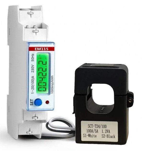
The example uses an EM115 MOD single-phase Modbus meter, but the same setup principle applies to other Modbus RTU devices.
- Meter manual used in this example: EM115-MOD Manual (PDF)
2. DIP Configuration Switches
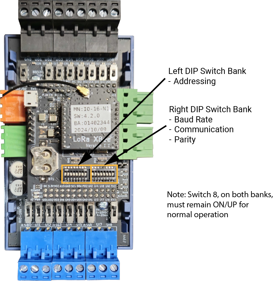
There are 2 banks of small DIP switches (8 DIP Switches per bank) under the cover of the Rubix iO-16 that are used to configure the modbus and LoRa functionalities of the iO module.
2.1 Left Bank DIP Switches - Modbus Addressing
The Left Bank of DIP Switches (labelled SW2) is used to set the address of the Rubix iO 16. The value is set as a binary number (the lowest digit is DIP #1) plus 1 using DIP Switches 1 to 7. See the table below for examples of address settings.
Switch Settings - 1 = DIP switch UP, and 0 = DIP switch DOWN. DIP switch #8 must remain ON/UP/1 for normal operation.
| [Dip-Switch: 1, 2, 3, 4, 5, 6, 7] | Device ID/ Address (as binary number+ 1) |
|---|---|
| Switch Setting | Device ID/ Address |
| 0000000 | 1 |
| 1000000 | 2 |
| 0100000 | 3 |
| 1100000 | 4 |
| 0010000 | 5 |
| 1010000 | 6 |
| 0110000 | 7 |
| 1110000 | 8 |
| 0001000 | 9 |
| 1001000 | 10 |
2.2 Right Bank DIP Switches - Modbus Communication Parameters
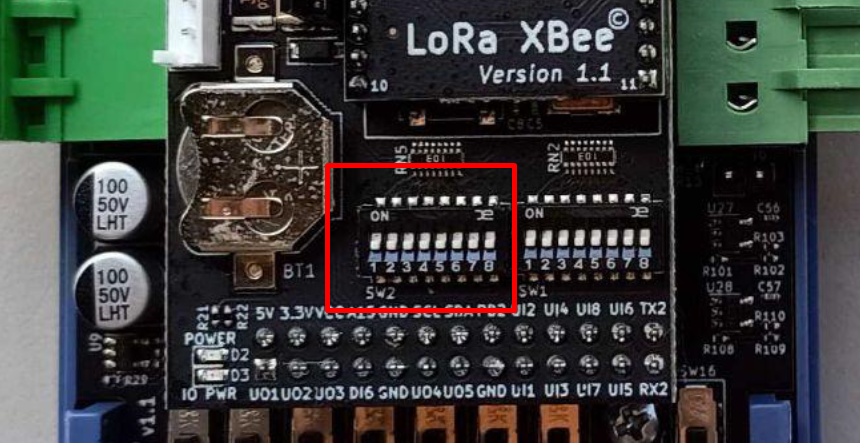
The Right Bank of DIP Switches (labelled SW1) is used to configure the communications functions of the Rubix iO 16.
Switch Settings - 1 = DIP switch UP, and 0 = DIP switch DOWN. DIP switch #8 must remain ON/UP/1 for normal operation.
| [Dip-Switch: 1, 2] | |
|---|---|
| Switch Setting | Operation Mode |
| 00 | RS485 (Wired) |
| 10 | LoRa® Wireless* |
| 01 | RS485 -> LoRa® Passthrough** |
| 11 | Settings Reset*** |
| [Dip-Switch: 3, 4, 5] | |
| Switch Setting | Baud Rate |
| 000 | 38400 |
| 100 | 9600 |
| 010 | 19200 |
| [Dip-Switch: 6, 7] | |
| Switch Setting | Parity |
| 00 | None |
| 10 | Even |
| 01 | Odd |
3. Passthrough Example 1
This example shows how to set up a Rubix iO-16 as a Modbus passthrough device for a single-phase Modbus meter with the following settings:
- Baud rate: 9600
- Modbus address: 1
- Parity: None
3.1 Hardware setup - Rubix iO-16
Only the Modbus device's addressing is required on the Rubix platform during modbus passthrough mode. The Rubix iO-16's address can be disregarded, therefore the dip switches on the left bank (SW2) can all be set down (except switch 8 must remain up).
Left bank DIP switches:
| Left Bank Switch | Position | Function |
|---|---|---|
| 1 | Down | Modbus Addressing |
| 2 | Down | Modbus Addressing |
| 3 | Down | Modbus Addressing |
| 4 | Down | Modbus Addressing |
| 5 | Down | Modbus Addressing |
| 6 | Down | Modbus Addressing |
| 7 | Down | Modbus Addressing |
| 8 | Up | Always Up |
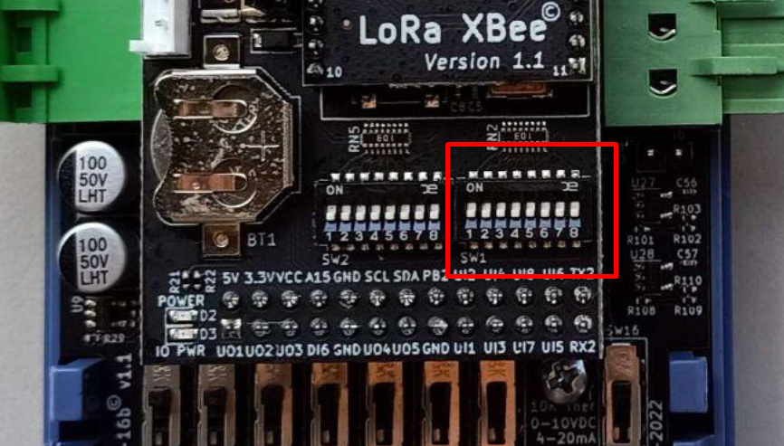
On the right bank (SW1) of the Rubix iO-16, set the dip switch settings to match the meter's baud rate (9600) and parity (None). The communication mode must be set to passthrough mode.
Right bank DIP switches:
| Right Bank Switch | Position | Function |
|---|---|---|
| 1 | Down | Comm Mode |
| 2 | Up | Comm Mode (Passthrough) |
| 3 | Up | Baud Rate (9600) |
| 4 | Down | Baud Rate |
| 5 | Down | Baud Rate |
| 6 | Down | Parity |
| 7 | Down | Parity |
| 8 | Up | Always Up |
3.2 Software setup - Rubix Platform
3.2.1 Create the wireless Modbus network
- On the controller level, under
drivers, click the create to select and download and install the relevant network.
 - Select the Modbus Network. This will download the appropriate modules and drivers.
- Configure the Modbus Network. Make sure that the parameters are same with the devices you will add on the network. Use the following network settings for this example:
- Network Name: Assign a name
- Tick enable: enabled
- Transport Type: serial
- Serial Port: /data/socat/serialBridge1
- Serial parity: none
- Serial baud rate: 38400 (even though the meter baud rate is 9600, the iO module will convert it to 38400 for LoRa transmission)
- Serial Data Bit: 8
- Serial Stop Bits: 1
- Max Poll Rate (ms): 6000 (for iO modules in LoRa mode)
- Once all the settings are added click on Create Network button. This will now create the Modbus and network. Now open the Modbus network to add a device.
3.2.2 Add the Modbus device
When adding the Modbus device in Rubix CE, set the device address to match the Modbus meter address.
Example: if the meter address is 1, set the device address to 1.
For this example, the device settings are as follows:
On Modbus Network, under
drivers, click the create new device.Fill out the details in the pop-up window with the correct information for the device you are adding. Ensure the Address ID is unique within the network and matches the Modbus meter address.
- Device Name: Assign a name
- Address ID: 1 (must match the Modbus meter address)
- Other fields can be left as default for this example.
Click
Saveto confirm.
3.2.3 Add the Modbus points
Add the points using the meter register map from the manufacturer manual.
Example points used in this guide:
- Voltage
- Frequency
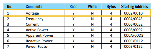
Locate the newly added device you want to add points to from the list under the Modbus network. Right-click to open its settings.
Click the Create
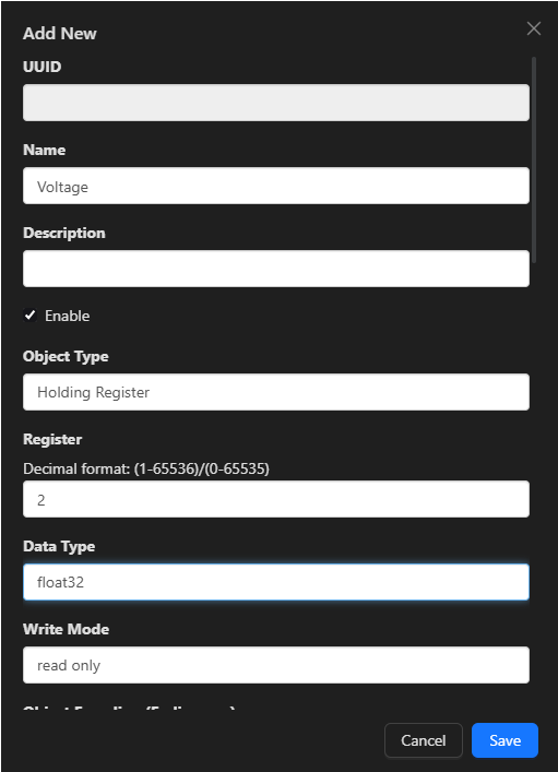
.Enter the point details in the pop-up window based on the device's manufacturer documentation for Modbus registers. See the following point and register map for this example.
- Point Name: Voltage (eg Voltage)
- Object Type: Holding Register
- Modbus Register: 2
- Data Type: float32
- Write Mode: Read Only
- Other fields can be left as default for this example.
Click the
Savebutton to finalize.
After points are added, verify values are updating and reading correctly.
4. Passthrough Example 2
This example shows how to set up a Rubix iO-16 as a Modbus passthrough device for a single-phase Modbus meter with the following settings:
- Baud rate: 9600
- Modbus address: 30
- Parity: Even
4.1 Hardware setup - Rubix iO-16
Only the Modbus device's addressing is required on the Rubix platform during modbus passthrough mode. The Rubix iO-16's address can be disregarded, therefore the dip switches on the left bank (SW2) can all be set down (except switch 8 must remain up).
Left bank DIP switches:
| Left Bank Switch | Position | Function |
|---|---|---|
| 1 | Down | Modbus Addressing |
| 2 | Down | Modbus Addressing |
| 3 | Down | Modbus Addressing |
| 4 | Down | Modbus Addressing |
| 5 | Down | Modbus Addressing |
| 6 | Down | Modbus Addressing |
| 7 | Down | Modbus Addressing |
| 8 | Up | Always Up |
On the right bank (SW1) of the Rubix iO-16, set the dip switch settings to match the meter's baud rate (9600) and parity (Even). The communication mode must be set to passthrough mode.
Right bank DIP switches:
| Right Bank Switch | Position | Function |
|---|---|---|
| 1 | Down | Comm Mode |
| 2 | Up | Comm Mode (Passthrough) |
| 3 | Up | Baud Rate (9600) |
| 4 | Down | Baud Rate |
| 5 | Down | Baud Rate |
| 6 | Up | Parity (Even) |
| 7 | Down | Parity |
| 8 | Up | Always Up |
4.2 Software setup - Rubix Platform
4.2.1 Create the wireless Modbus network
- On the controller level, under
drivers, click the create to select and download and install the relevant network. - Select the Modbus Network. This will download the appropriate modules and drivers.
- Configure the Modbus Network. Make sure that the parameters are same with the devices you will add on the network. Use the following network settings for this example:
- Network Name: Assign a name
- Tick enable: enabled
- Transport Type: serial
- Serial Port: /data/socat/serialBridge1
- Serial parity: even
- Serial baud rate: 38400 (even though the meter baud rate is 9600, the iO module will convert it to 38400 for LoRa transmission)
- Serial Data Bit: 8
- Serial Stop Bits: 1
- Max Poll Rate (ms): 6000 (for iO modules in LoRa mode)
- Once all the settings are added click on Create Network button. This will now create the Modbus and network. Now open the Modbus network to add a device.
4.2.2 Add the Modbus device
When adding the Modbus device in Rubix CE, set the device address to match the Modbus meter address.
Example: if the meter address is 30, set the device address to 30.
For this example, the device settings are as follows:
On Modbus Network, under
drivers, click the create new device.Fill out the details in the pop-up window with the correct information for the device you are adding. Ensure the Address ID is unique within the network and matches the Modbus meter address.
- Device Name: Assign a name
- Address ID: 30 (must match the Modbus meter address)
- Other fields can be left as default for this example.
Click
Saveto confirm.
4.2.3 Add the Modbus points
Add the points using the meter register map from the manufacturer manual.
Example points used in this guide:
- Voltage
- Frequency
Locate the newly added device you want to add points to from the list under the Modbus network. Right-click to open its settings.
Click the Create
.Enter the point details in the pop-up window based on the device's manufacturer documentation for Modbus registers. See the following point and register map for this example.
- Point Name: Voltage (eg Voltage)
- Object Type: Holding Register
- Modbus Register: 2
- Data Type: float32
- Write Mode: Read Only
- Other fields can be left as default for this example.
Click the
Savebutton to finalize.
After points are added, verify values are updating and reading correctly.