Optical Sensor Installation and Commissioning Guide
1. Powering and Installing the Gateway
This section will outline the process required to power and install the gateway.
If the gateway is already installed onsite please proceed to section 2.
1.1 Re-attaching the Aerials
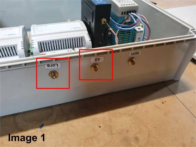
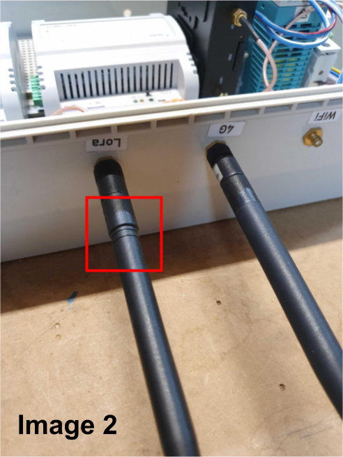
Before powering on the gateway, ensure the LoRa and 4G aerials are securely screwed into their correctly labeled ports on top of the gateway. The LoRa aerial is identifiable by two lines around its base (see Images 1 and 2).
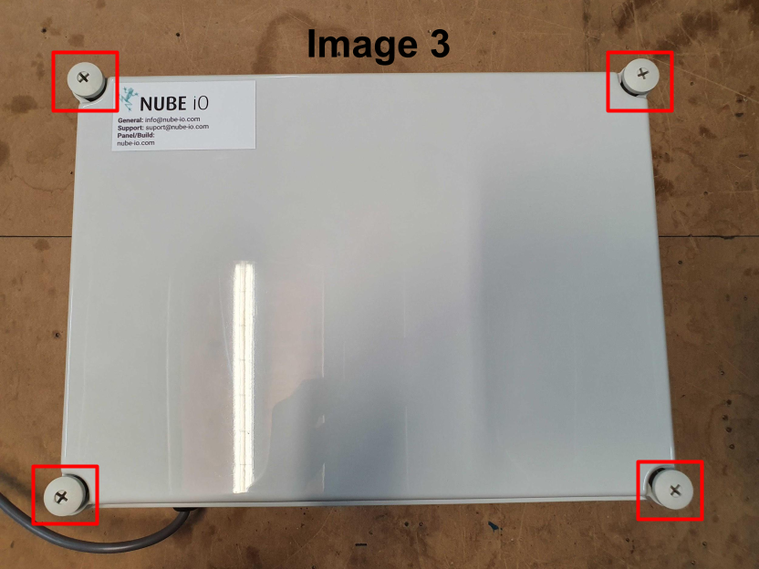
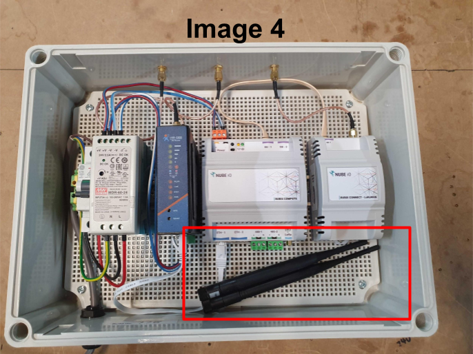
The aerials are stored inside the enclosure during shipping to prevent damage. To access them, unscrew the four corner screws on the enclosure lid (these are only finger-tight when shipped). (See images 3 and 4)
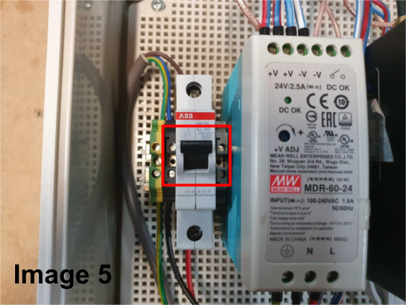
During this step confirm the circuit breaker is in the 'ON' position before re-installing the enclosure lid. The up position is when the circuit breaker is ON. (See Image 5)
1.2 Installing the Gateway
If securing the gateway to a wall, use four fixings - one in each corner of the enclosure. The choice of fixings will depend on the wall material.
If wall-mounting is not required, ensure the gateway is stored in a safe and secure location, free from any stress on the power cable.
1.3 Powering the Gateway
The gateways come with a pre-wired 3-pin plug. Simply connect this to a power outlet and switch it on. Allow up to 5 minutes for the 4G router and Rubix Compute to power up completely.
2. Optical Sensor Activation
2.1 Optical Sensor Contents
Open the Optical sensor box and confirm the following components are present:
- Optical sensor
- 1 x Optical Pulse Cable (pre-wired to the Optical sensor)
- 1 x LoRa Antenna
- 1 x 3.6V Lithium Battery
- 2 x Adhesive Velcro Strips (Loop side pre-attached to the back of the Optical sensor)
- 1 x LoRa F to F Adapter
- 1 x 300mm LoRa Extension Cable
2.3 Optical Sensor Components
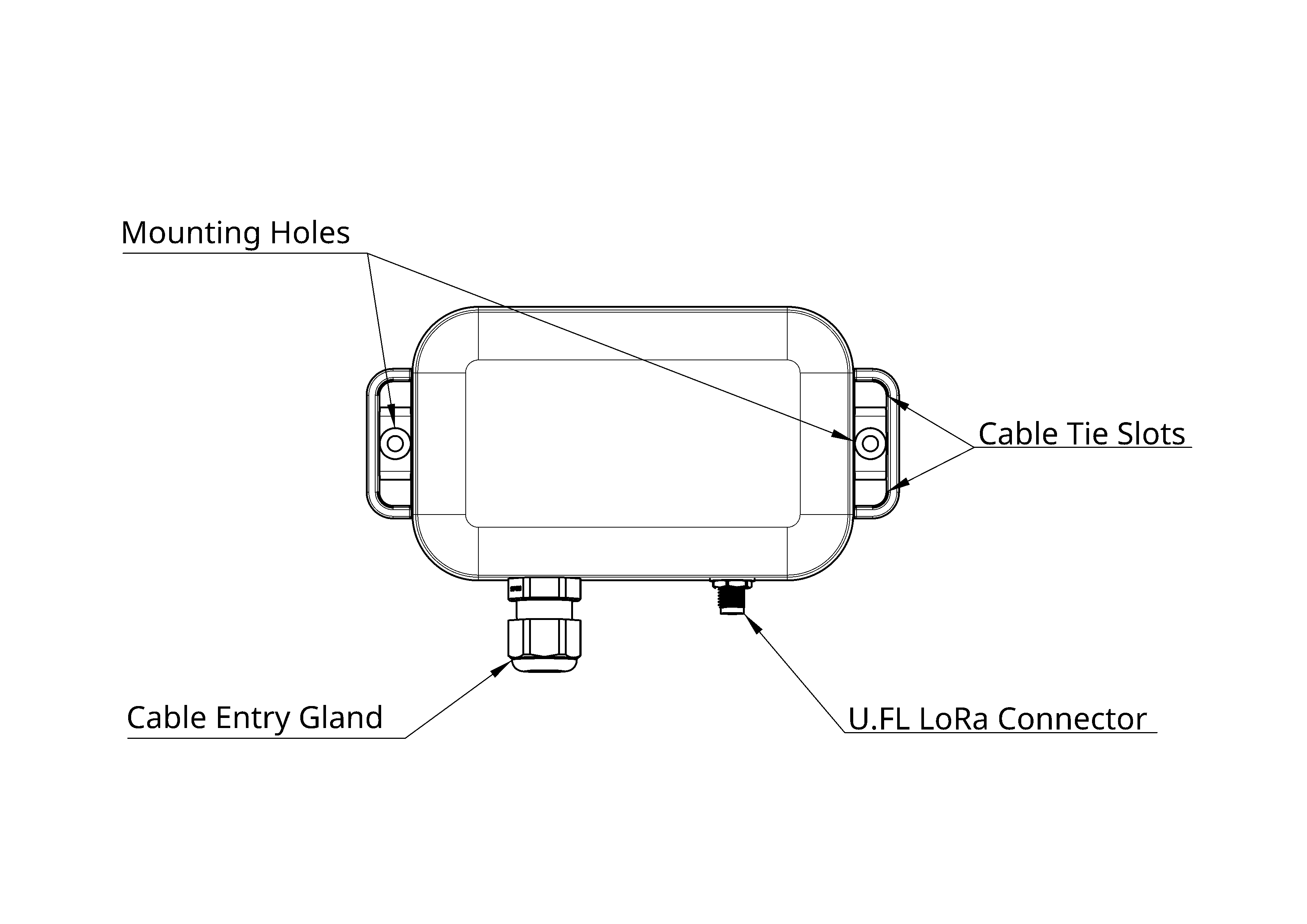
2.2.1 Front View
- U.FL LoRa Connector: Connects the LoRa antenna for wireless communication.
- Mounting Holes: For secure attachment using fixings.
- Cable Tie Slots: For secure attachment using cable ties.
- Cable Entry Gland: Allows the optical pulse cable to pass through while maintaining a weatherproof seal.
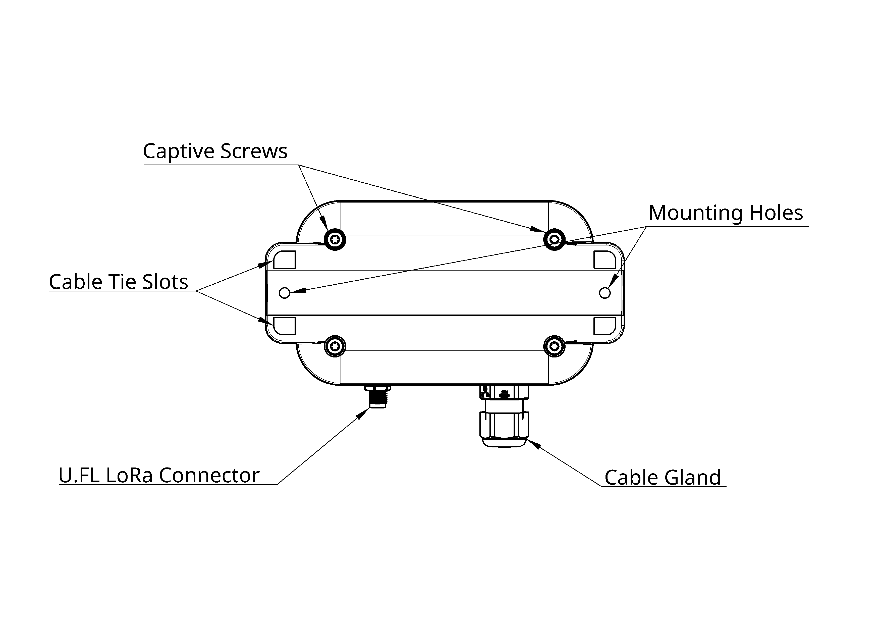
2.2.2 Rear View
- U.FL LoRa Connector: Connects the LoRa antenna for wireless communication.
- Mounting Holes: For secure attachment using fixings.
- Cable Tie Slots: For secure attachment using cable ties.
- Captive Screws: To sercure the optical sensor to the backplate and prevent tampering.
- Cable Entry Gland: Allows the optical pulse cable to pass through while maintaining a weatherproof seal.
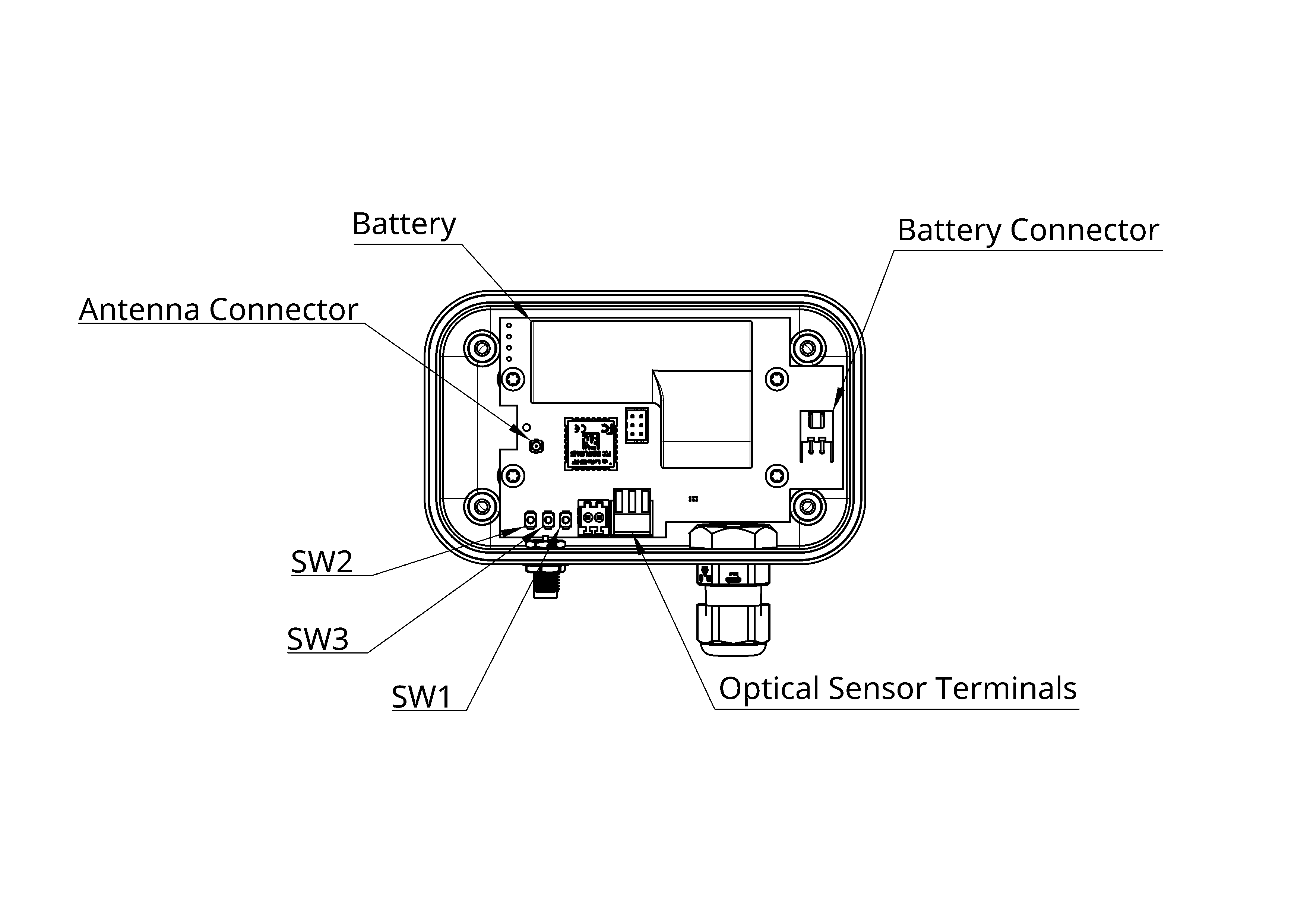
2.2.3 Internal View
- Battery: 3.6V Lithium Battery powers the Optical sensor.
- Battery Connector: Connects the battery to the Optical sensor.
- Antenna Connector: Connects the U.FL LoRa Connector to the PCB for wireless communication.
- Optical Sensor Terminals: Connects the optical pulse cable to the Optical sensor.
- SW1: USER. The USER button transmits data upon a press-and-release action; releasing the button immediately sends the data via LoRa.
- SW2: RESET. The RESET button resets the entire program and resets the pulse counting to 0.
- SW3: BOOT. Spare button for future use.
2.3 Activating the Optical Sensor
Once the gateway is powered, you may also power the Optical sensor by connecting the battery to its terminal. The Optical sensors will restart their data transmission and automatically join the server. Refer to section 2.2.3 Internal View for the location of the battery and battery connector.
3. Sensor Installation
After restoring power to both the gateway and Optical, the optical pulse cable can be stuck over the OP1 or Pulse 1 terminal on the EDMI Electrical meter using the following steps:
- For optimal performance, install the aerial vertically, ensuring it is free from obstructions.
- When mounting the Optical sensor with Velcro, ensure the surface is clean and dry. Peel the backing strips off one side of the Velcro pads and stick them to the back of the Optical sensor. Then, remove the remaining backing strips and press the Optical sensor firmly against the wall or surface where it will be mounted. Maintain firm pressure for approximately 30 seconds to ensure a strong bond.
- When mounting the Optical sensor with wall fixings, position it close enough to the EDMI meter to prevent cable damage from sagging, potential trips, or tangling. Hold the Optical in place and mark the wall for drilling. Drill the holes and secure the Optical to the wall using appropriate fixings ensuring it is free from obstructions.
- If using cable ties, the cable ties can be looped through the mounting holes on each side and then looped around the mounting surface. Ensure the cable ties are tight enough to hold the Optical securely in place, but not so tight that they damage the cable or the Optical sensor.
- Clean the area around the OP1 or Pulse 1 LED on the meter with a clean cloth to remove any dust or debris.
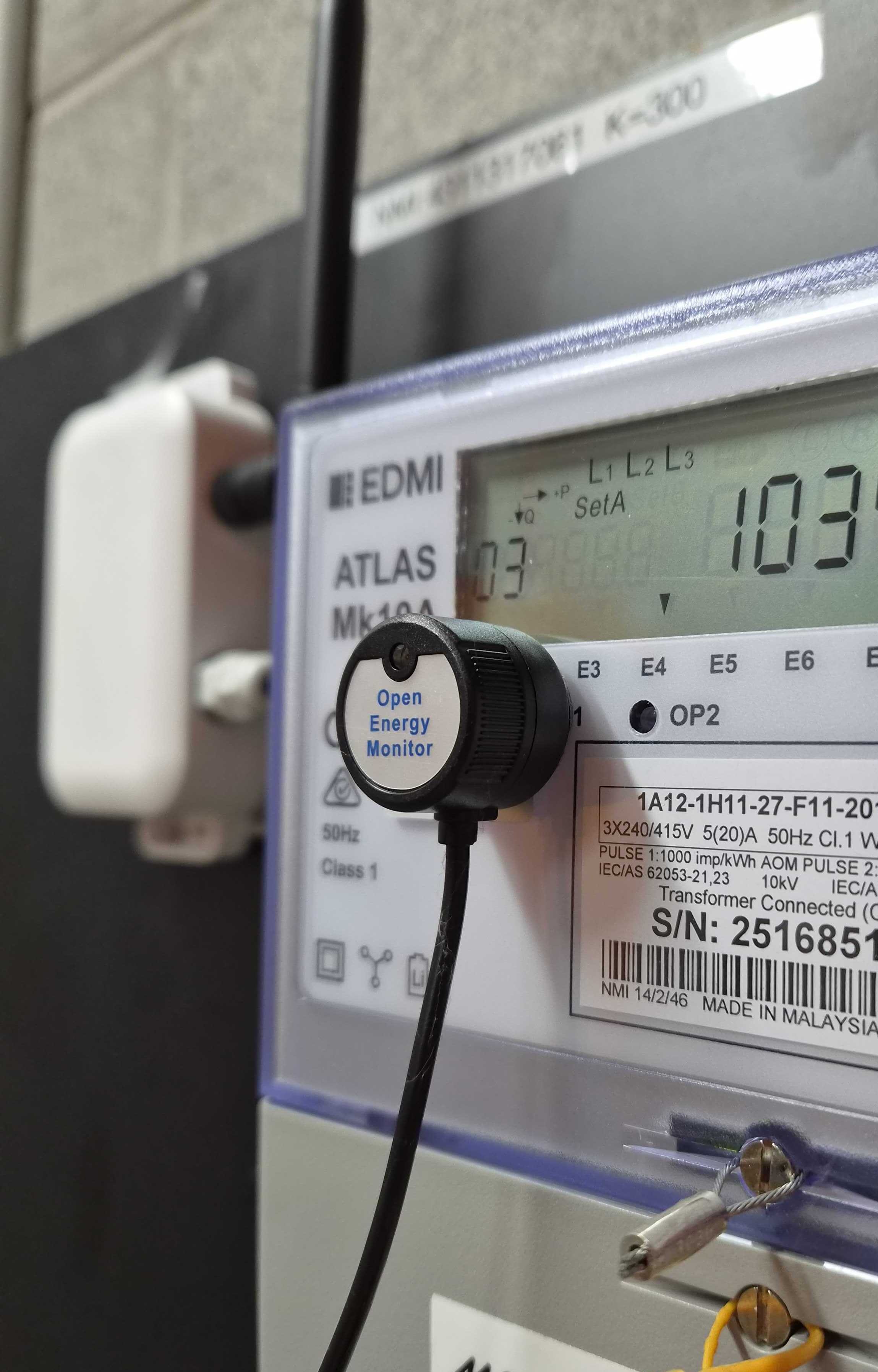
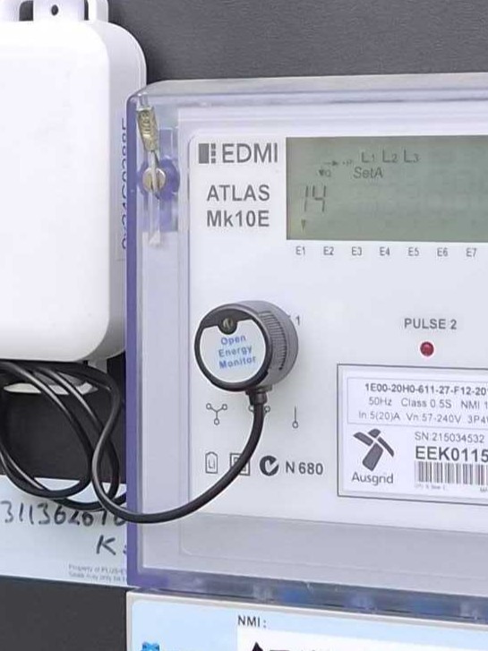
- Peel the backing off the optical pulse cable and stick it over the OP1 or Pulse 1 LED on the meter. Ensure the cable is aligned with the LED and pressed firmly to ensure a good connection. Insert Image
- Once the optical pulse cable is in place, check that it is securely attached and not loose. If necessary, use cable ties to secure the cable to the meter or surrounding area to prevent it from moving or becoming dislodged.
- If necessary, use the LoRa SMA Adapter and LoRa Extension Cable to extend the LoRa Antenna away from the Optical sensor and the meter to a more suitable location (eg external to the switchboard). Ensure the extension cable is securely connected to both the Optical sensor and SMA adapter, and that it is not loose or dangling. If required seal the adaptor penetration point with silicone to prevent water ingress and use cable ties to secure the extention cable to the surrounding area to prevent it from moving or becoming dislodged.
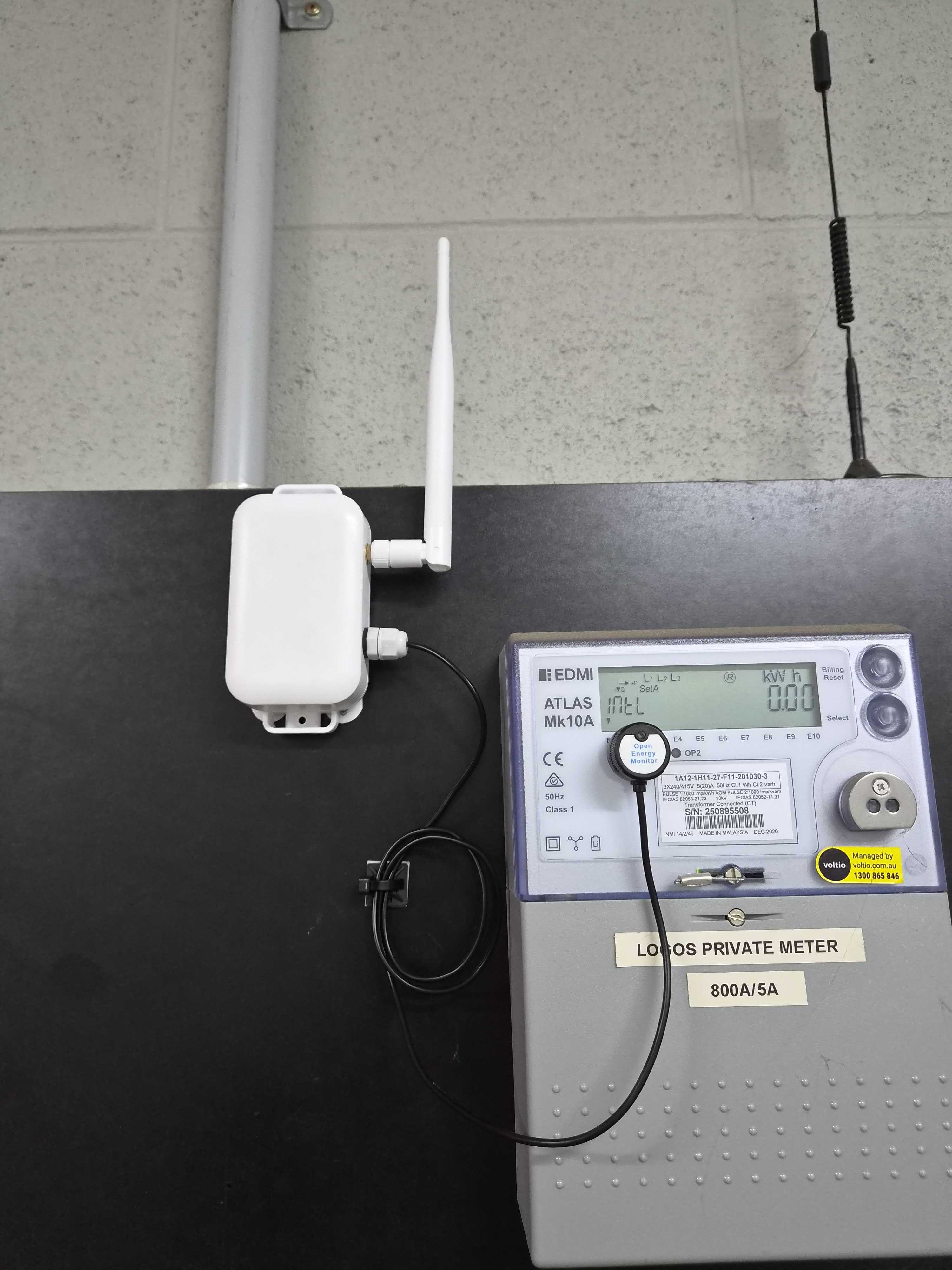
See following images for examples of the Optical sensor installation and LoRa antenna extension.
Example 1 (Inside Main Switchroom)
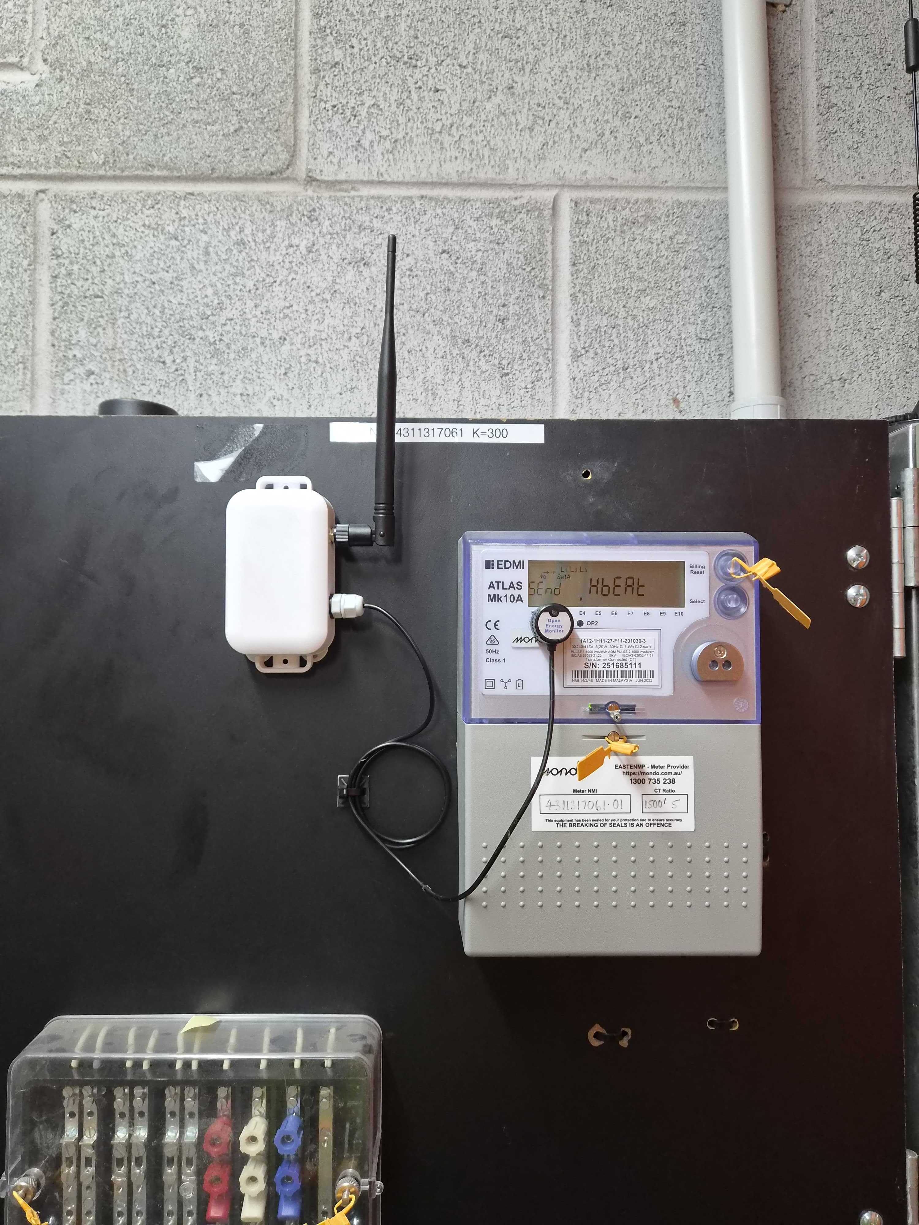
Example 2 (Inside Main Switchboard with LoRa Antenna Extension)
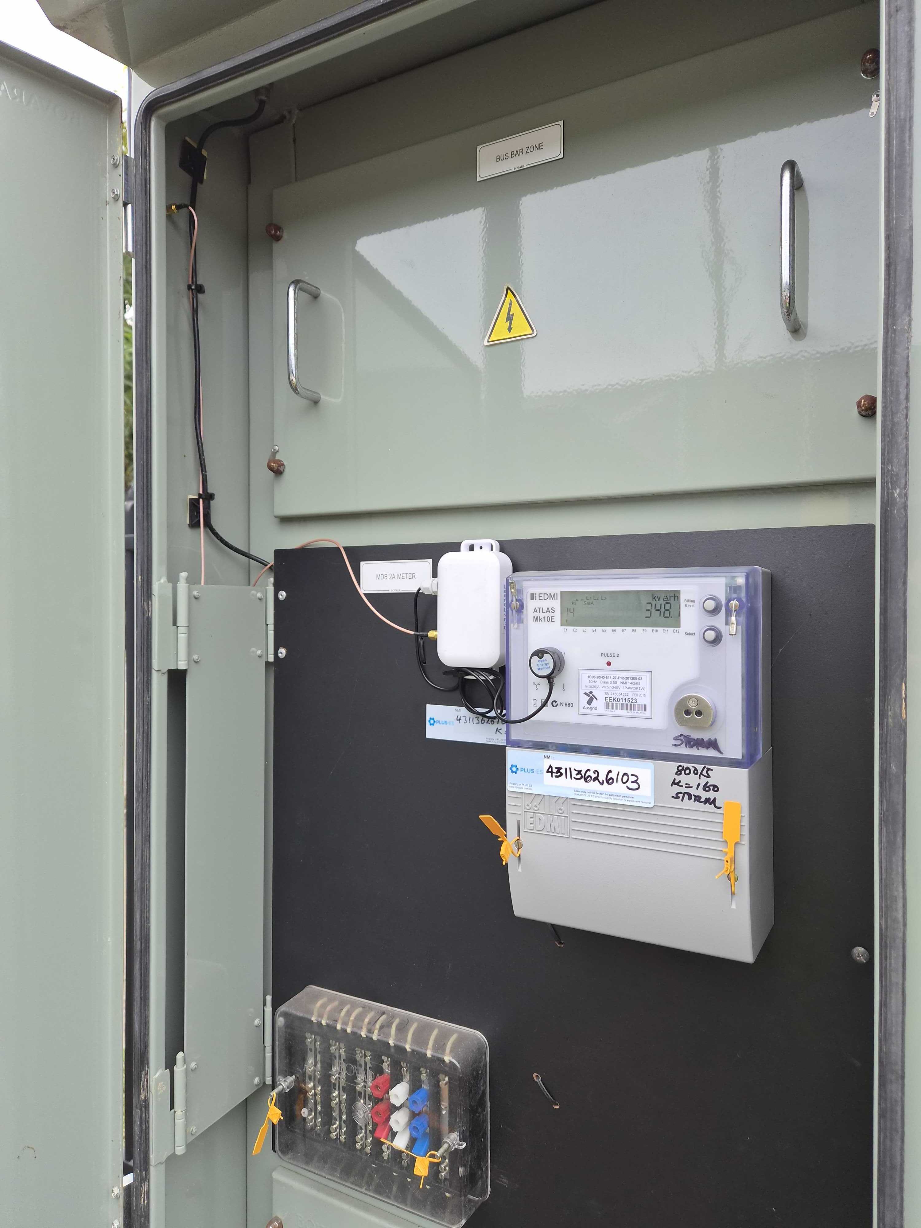
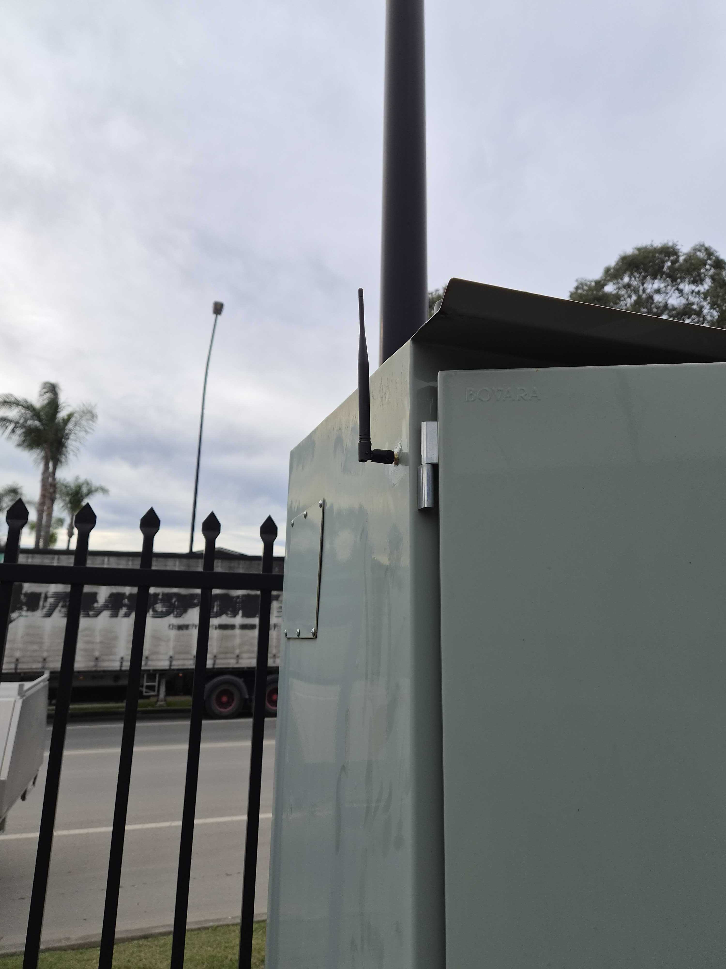
Example 3 (OP1 and Pulse1 Mounting)
4. Commissioning
After installation, the Optical sensor requires a signal check and a Rate of Change Validation test. This test aligns the calculated and physical meter readings, ensuring they remain within tolerance by recording start and end values as electrical usage (kWh) accumulates on the meter.
4.1 Optical Sensor Points
The following points are available for the Optical sensor in Rubix CE once the sensor has been added to the LoRaRaw network as a Rubix device and has joined the gateway. These points are used for commissioning and troubleshooting the Optical sensor.
- rssi - Received Signal Strength Indicator
- snr - Signal to Noise Ratio
- uvp-1 - Interval
- uvp-2 - Battery
- uvp-3 - Payload count
- uvp-6 - Pulse count
4.2 Optical Signal Strength Check
4.2.1 RSSI
For optimal performance, the Optical sensors Received Signal Strength Indicator (RSSI) should not exceed -115. An RSSI greater than this may lead to signal dropouts and data loss. For instance, an RSSI of -121 indicates poor signal and necessitates the installation of a more suitable antenna and/or antenna location. If the RSSI is poor, try improving the signal by repositioning the Optical and/or the Gateway.
If the signal does not improve, please contact Nube-iO Support on 0499 949 449.
4.2.2 SNR
For optimal performance, the Optical sensors Signal-to-Noise Ratio (SNR) should be greater than 0. For moderate performance, the SNR should be greater than -10. A low SNR may indicate high interference in the area, which can lead to signal dropouts and data loss. For instance, an SNR of -12 indicates high interference in the area and necessitates the installation of the LoRa antenna extension to a more suitable location.
If the signal does not improve, please contact Nube-iO Support on 0499 949 449.
4.2 Entering the Initial Meter Reading Values (Start Values)
To generate an accurate Calculated Meter Reading within the virtual system, each meter requires the input of specific 'Start Value' parameters. These parameters are:
- kWh Per Pulse
- Start Pulses
- Start Meter Reading (kWh on meter display)
Before entering any details, ensure the correct site is located on the Rubix CE platform and you are logged into the correct controller.
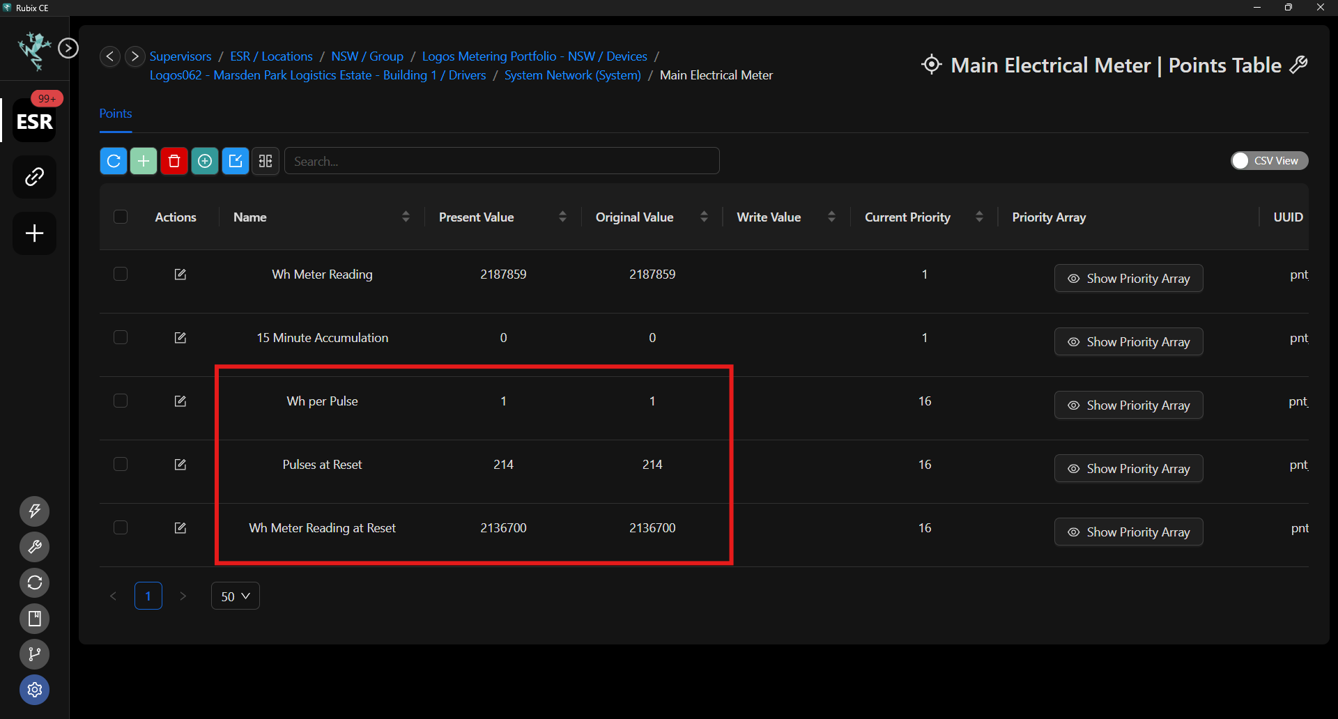
Enter values in the start values by right clicking on the point and then select 'write point'. This will open the priority array where the start value can be entered. Clicking the 'send' button will write this value into the program.
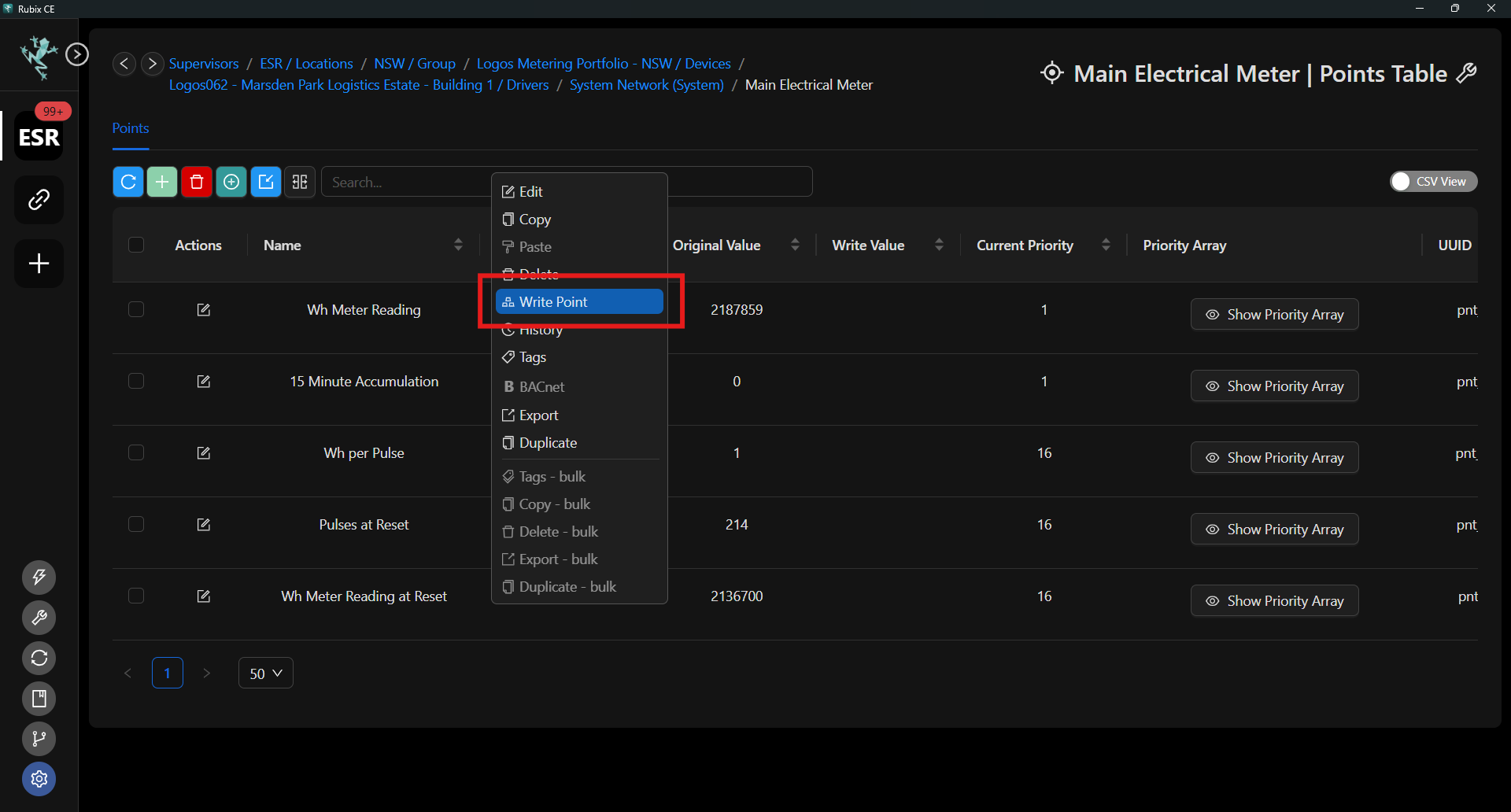
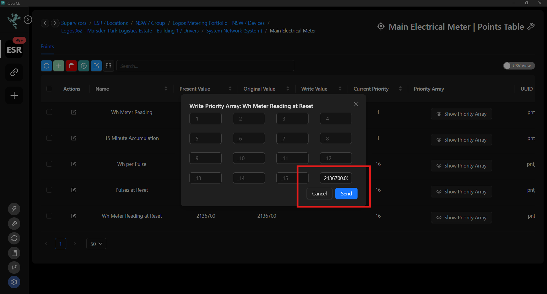
4.2.1 kWh Per Pulse
The "kWh per pulse" value is often expressed as a ratio (e.g.10 imp/kWh → 100 Wh per pulse), and can be found on the electricity meter's info display or in the meter's technical documentation.
Typical Mk10A and MK10E Pulse constants:
- 1000 imp/kWh → 1 Wh per pulse
- 100 imp/kWh → 10 Wh per pulse
- 10 imp/kWh → 100 Wh per pulse
- 1 imp/kWh → 1 kWh per pulse
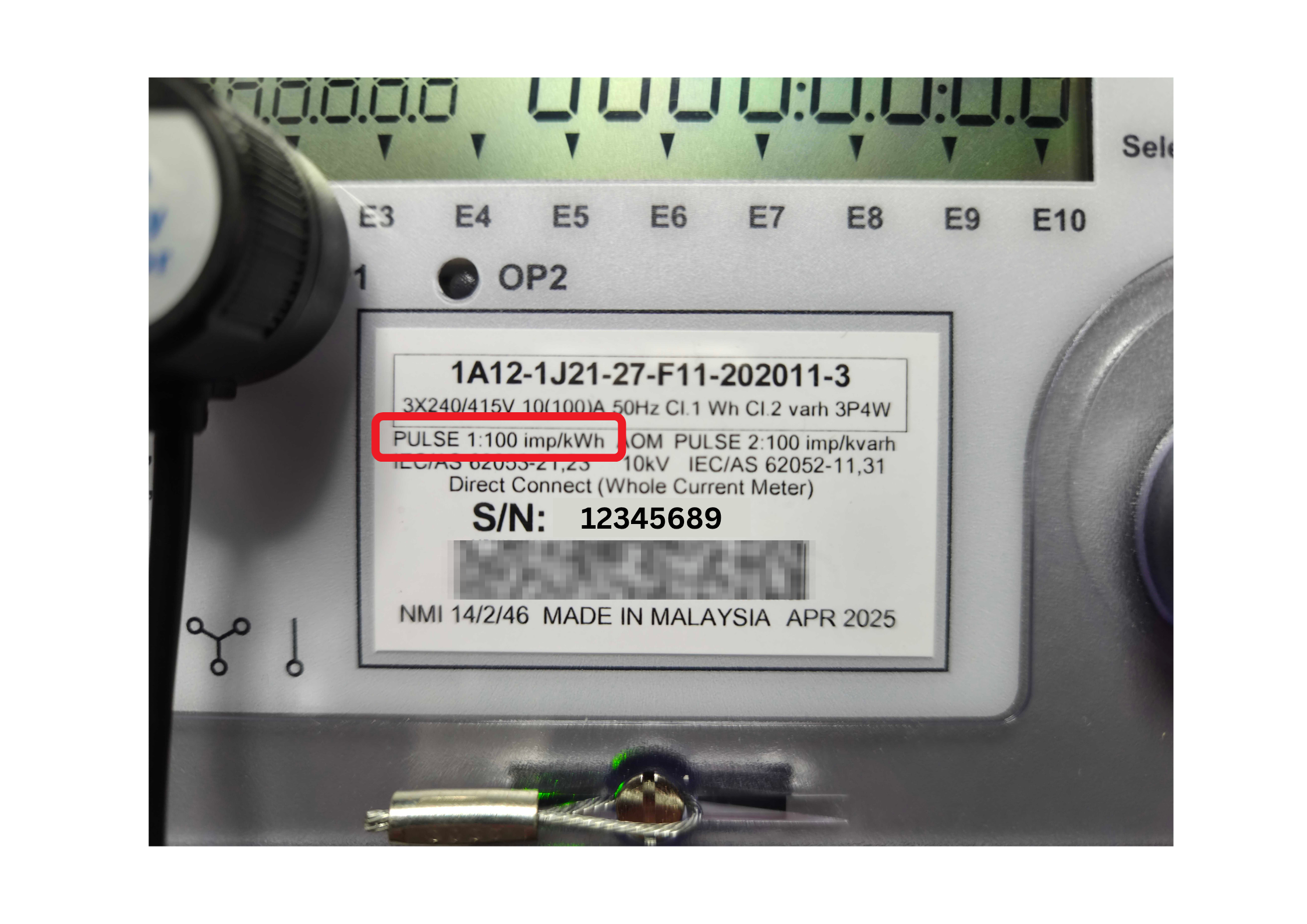
Note: The kWh per pulse value listed on the meter may differ from the real world value as it is dependent on the meter's configuration. If the kWh per pulse value is not known or different from the meter's label after the rate of change test, the value can be calculated by dividing the change in energy (kWh) by the change in pulse count. See formula below.
Example using the following values:
| Parameter | Value |
|---|---|
| Start Pulses | 214 |
| Finish Pulses | 5861 |
| Start kWh | 2136.7 |
| Finish kWh | 2142.4 |
Calculation: (2142.4 - 2136.7) / (5861 - 214) = 5.7 / 5647 ≈ 0.00101 kWh per pulse, or 1 Wh per pulse.
4.2.2 Start Pulses
The start pulses also need to be entered into the Rubix CE software when commissioning the meter. This value is found in the most up-to-date optical sensor payload on point 'uvp-6'. This value aligns the start meter reading with the current pulses.
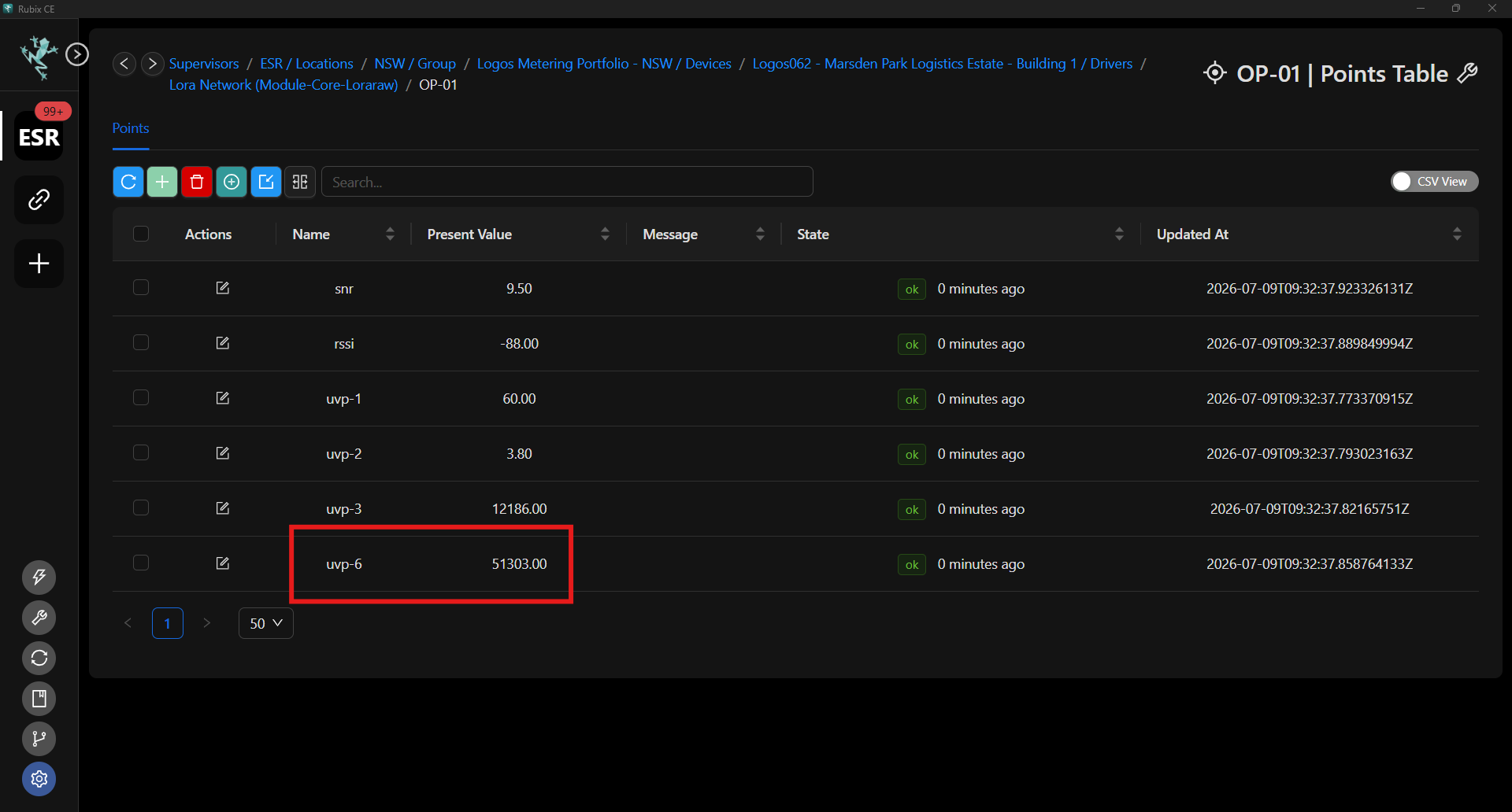
4.2.3 Start Meter Reading (kWh on meter display)
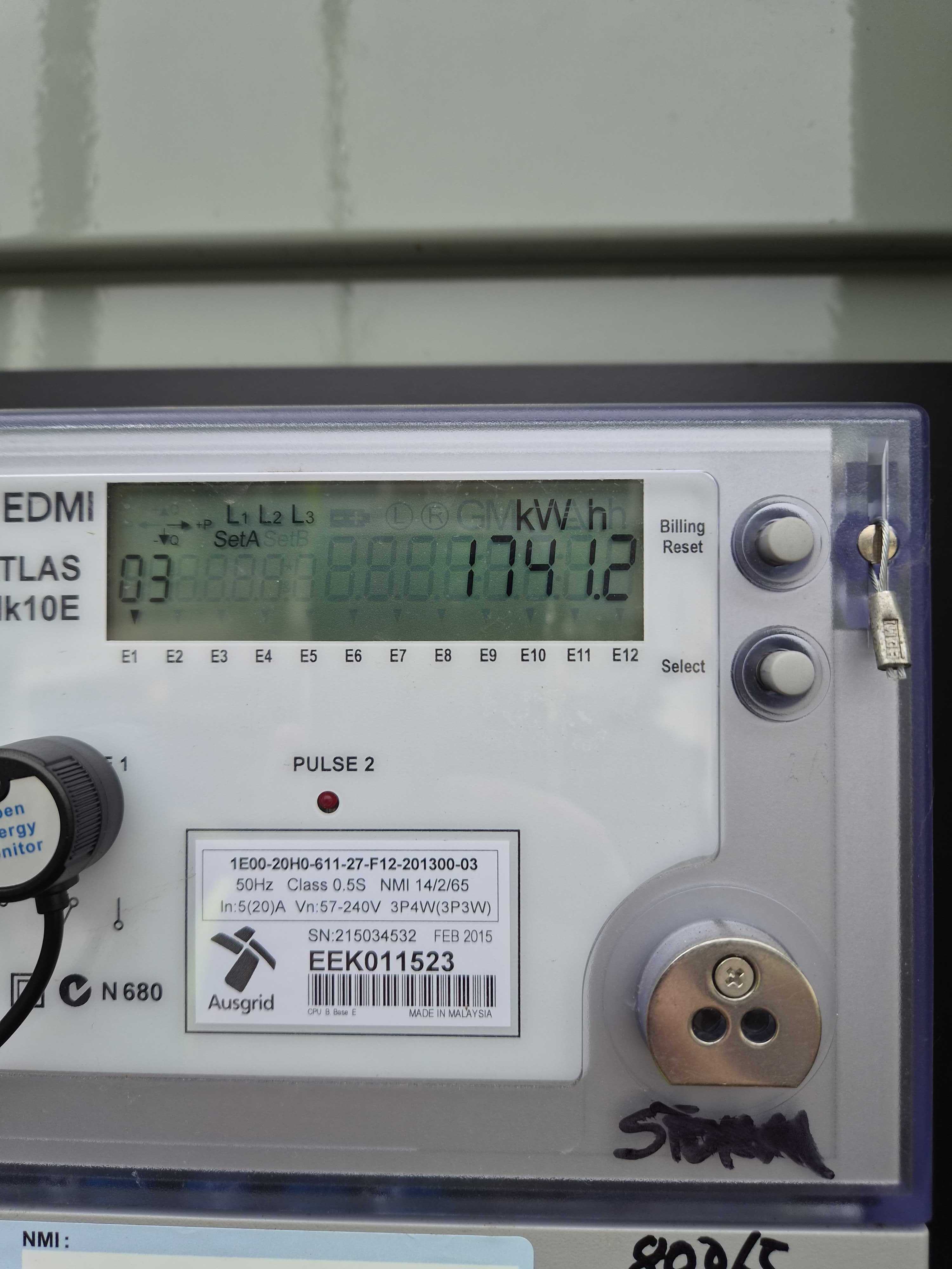
The Start Meter reading needs to be entered into Rubix CE to match the physical meter reading at the start time of the commissioning process. This needs to be as accurate as possible as this will be the value that accumulates in the software moving forward. See example below for meter reading of 1741.2 kWh.
The start meter reading MUST be entered as Wh. For example, if the meter reading is 1741.2 kWh, enter 1741200 Wh into the Rubix CE software.
4.3 Rate of Change Test
A Rate of Change test must be carried out in order to verify that the physical meter and the start meter values entered in the Rubix CE program move in alignment when water moves through the meter. This test needs to be done to verify that the physical and calculated readings do not drift apart over time.
4.4 Recording the Finish Commissioning Values
Once adequate electrical usage has accumulated on the meter, record the final values on the commissioning sheet. These should include the RSSI, battery voltage, current pulses, physical meter reading, and calculated meter reading, and then cross-reference them with the physical reading.
4.4.1 RSSI (Received Signal Strength Indicator)
For optimal performance, the Optical sensors Received Signal Strength Indicator (RSSI) should not exceed -115. An RSSI greater than this may lead to signal dropouts and data loss. For instance, an RSSI of -121 indicates poor signal and necessitates the installation of a more suitable antenna and/or antenna location. If the RSSI is poor, try improving the signal by repositioning the Optical and/or the Gateway.
4.4.2 Battery Voltage
The battery voltage from the Optical sensor device data should be greater than 3.6 volts.
4.4.3 Current Pulses
This current pulses value should be recorded at the time of taking the final reading for comparison with the initial pulse value.
4.4.4 Physical Meter Reading and Calculated Meter Reading
For the Rate of Change test to pass, the recorded physical and calculated readings must be compared and fall within an acceptable tolerance. This tolerance is determined by the pulse-per-kWh value. For instance, if the meter registers 10 imp/kWh → 100 Wh per pulse, the physical and calculated readings should not differ by more than 100 Wh.
If the readings are outside of this tolerance refer to the note in section 4.2.1 kWh Per Pulse and use the formula to calculate the correct kWh per pulse value. If the readings are still outside of tolerance, please contact Nube-iO Support on 0499 949 449.